Stepper motor basics
A standard bipolar stepper-motor usually will have 1.8 degree steps. That will be 200 steps per revolution. It has two motor windings (phase A and B) that must be controlled. The motor is rated at some maximum current per phase. That means, it will be the maximum current in each winding.
If we look at the data sheet for a specific motor we find:
Maximum current pr phase: 1.4 A
Resistance per phase: 4.2 Ohms
Inductance per phase: 15 mH
Thus, if you put 5.88V (~6V) across a phase, it will reach its maximum current. V = R * I = 4.2Ω * 1.4A = 5.88V
Normally we can control this current with a resistor in serial with the phase or we can use PWM (Pulse with Modulation). If we have 12V for our motor, it will have to be at about 50% duty cycle to meet the maximum rating.
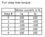
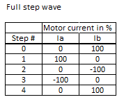
A standard full step cycle consist of 4 steps. Thesesteps must the be repeated over and over again, to make the motor turn. If we reverse the cycle the motor will turn in reverse.
As we see from the table above, we will have to inverse the polarity of the phase voltage every other step. To do this we can use a standard H-bridge. With two H-bridges we can control the current in both phases.
PWM, constant current and chopper drivers
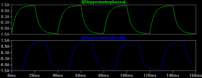
The first problem to overcome is the inductance in each windings. In the data sheet it says 15 mH for this particular stepper motor. This inductance will cause the current to change slowly, and it will prevent fast stepping rates. If we look at a simple simulation in LTSpice, only considering the inductance and not any back EMF or other things in the motor, it will look like this:
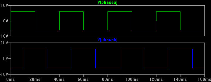
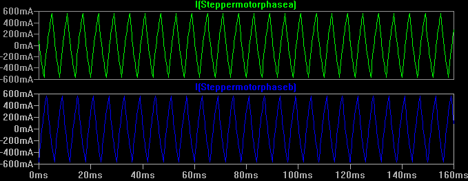
At 6V, if the frequency in each phase is 25Hz, the voltage and current flow will look like this:
At 166 Hz and 6V the current will look like this:
As we can se from the plots above, we will not be able to feed the proper amount of current for the motor at higher stepping-rates. Eventually the stepper motor will stall and just stop at some point if we further increase the step rate.
166Hz is not that fast. The motor will do 4 steps for each period. Each period is 6ms. Time per revolution is then:
t=200/4*6ms = 0.3s
rpm = 60/0.3 = 200 (And then 2/3 of the torqu is gone. This is too slow for most applications)
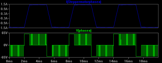
We need some higher voltage to force more current in the motor. But we must ensure the current will not exceed the maximum rating for the motor. The easiest way of doing this is to use a chopper driver for the motor. This will feed the motor the higher voltage until the current limit is reached. The stepper driver will the use PWM to hold the current constant. It will look something like this at 60V and 166Hz:
We can than increase the step rate without burning the motor. The power dissipation will be the same because P=I*I*R = 1.4A*1.4A*4.2Ohm = 8.2W for each phase. For the motor it will be Pa+Pb= 16.4W
Half step and micro-step
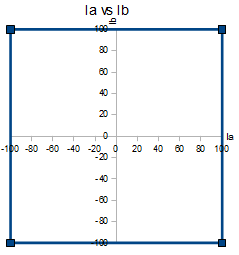
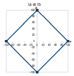
If we look at the phase currents in another way (phase diagram), by plotting the current of phase A vs the current of phase B, we will have this diagram:
In the diagram above the first step will be the point at the upper right, step two will be at bottom right, step tree at bottom left and step four will be at the top left. If we follow the steps from 1-4 the plots will go clockwise in the diagram.
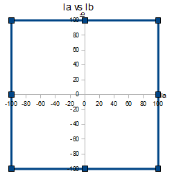
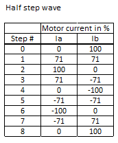
In half step the current table will look like this:
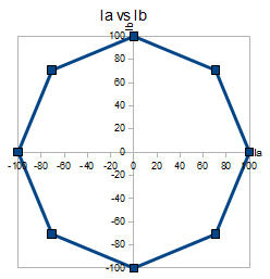
And the phase diagram will look like this.
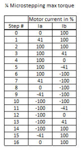
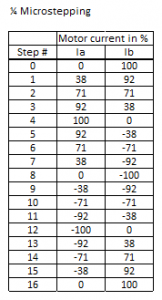
At 1/4 micro-stepping we will use this table:
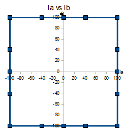
As we can see from the diagram above, we will have maximum torque possible for each micro step. But step number 1 have more torque than step 0, step 2 have more that step 1. The highest torque is the steps in the corners in the phase diagram. The torque is the length from center to the step-plot. This is because, if we energize both windings, the motor will have more torque than if we only energize one winding.
This will cause the motor to rotate a bit choppy, and there will be some vibrations. To overcome this problem, it’s better to use wave-stepping.
Wave micro-stepping
At the next table we see that only one phase is energized at a time. For full steps this method only decreases the torque, and does not really give any benefits.
With half step wave, we will see that every step is having the same torque, and the motor will run smoother:
At 1/4 micro-stepping we will just increase the resolution of the current table. The driver electronics will have to control the current according to the table for each micro-step.
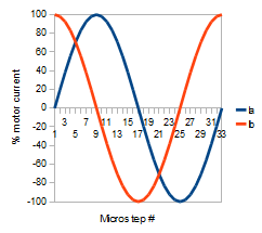
At 1/8 micro-stepping we will se that the current in each phase is actually a SIN and a COS. Each phase is 90 degree from each other.
The formulas for current in an 1/8 micro-stepping configuration are:
Ia = SIN(Stepnumber*360/32)Imax
Ib = COS(Stepnumber*360/32)Imax
For 1/16 microstepping it will be:
Ia = SIN(Stepnumber*360/64)Imax
Ib = COS(Stepnumber*360/64)Imax
For 1/32 microstepping it will be:
Ia = SIN(Stepnumber*360/128)Imax
Ib = COS(Stepnumber*360/128)Imax
Files:
http://www.lamja.com/blogfiles/SimpleChopperStepperMotorSimulation.asc






I would like to know how have you varied the phase of the two PWM signals? I can understand the phase difference is 90 deg. How it could be possible to generate such PWM signals 90 deg out of phase with each other in a Microcontrollers?
Its all generated by ‘direct digital synthesis’ – you start with the phase angle, look up the output value in a wave table (here sine/cosine curve) and output that. For the other phase just offset it by 90 degrees. Each step increments (or decrements) both phases by the step phase angle… A few additions and a table lookup, very easy at these frequencies.
This technique can be used at much high frequencies too with dedicated high-speed CMOS hardware, such as generating RF signals at 100’s of MHz.
Great explanation. Thanks! And I finally got introduced in a practical way to sine calculations. Since I’m missing some basics in that field this is highly interesting.
I have got the full and half stepping implementing on my stepper motor successfully but not able to program for the microstepping.I saw this tutorial but how to program for the microstepping.
Can you give me any sample code as a reference for the microstepping?
Great job. Very good explanation, but i have a question:
What is the frequency for the PWM ?
Normally I would have a PWM above what humans can hear, so from 20kHz and up. Else you canr hear the humming from the motor.
Please tell me how to implement micro stepping stepper motor using PIC microcontroller and H-bridge driver IC.
Hi. You’ll need two H-bridges that you can control the current from the PIC. Then you program the PIC to deliver different amount of current to each windings of the motor for each microstep.
what is THB_INV, THA_INV use for? i saw it conect to gnd
DMA, DMB jumper ??
thanks and regards
I guess you meant to comment on the Lamjastep-schematic. THx and THx_INV is just some labels, and is the Trigger High or Trigger Low signals. They determine how the decay for the PWM works. If THx (inverse of THx_INV) is on, the current error is so much that the current should reverse. if TL is on,its so low that it should reverse. In between, the H-bridge is just freewheeling. DMx jumper (Decay Mode) is used to disable the freewheeling part. DMx off = “Mixed kind of decay”, and on = “Fast decay”.
Great explanation. Thanks!