There are a lot of ways to create your own PCB’s at home. I have used the toner transfer method for a while, but it’s a pain to use the ironing iron and then dissolve the paper and so on. Some of the methods are:
– Toner transfer and etching
– Isolation routing with CNC
– Draw with a permanent marker directly on to the copper clad and etch
– UV light, photoresist PCB copper clad, transparency and etching
I have always wanted to try a CNC to mill a PCB (isolation Routing). When I finally got myself a 3D-printer, I could give it a try. But it was not easy. The Copper clad has to be compleatly flat, there is a lot of noise, it’s a BIG mess, and the 3D-printer is not rigid enough. So I combined permanent marker with isolation routing. Or sort of.
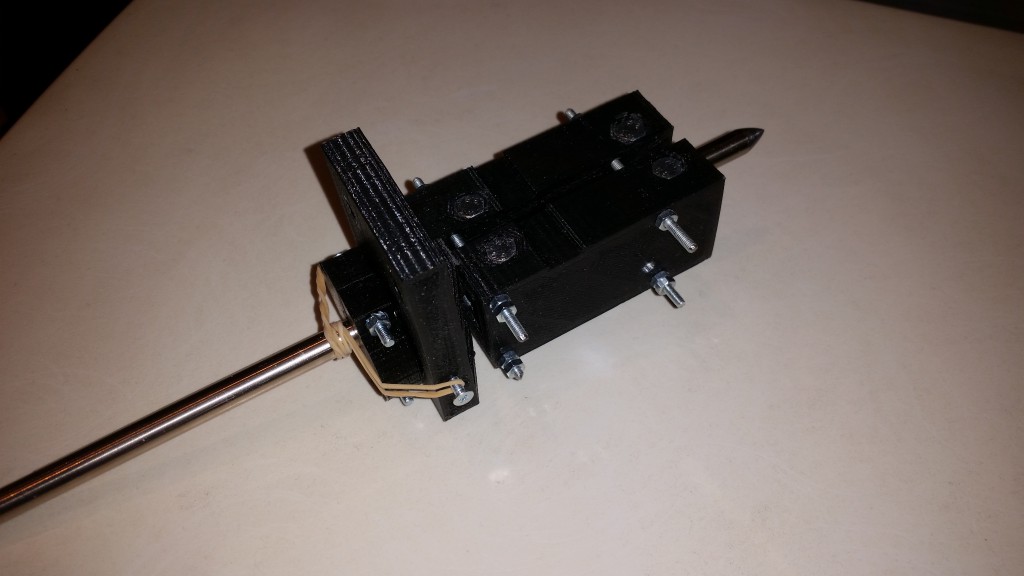
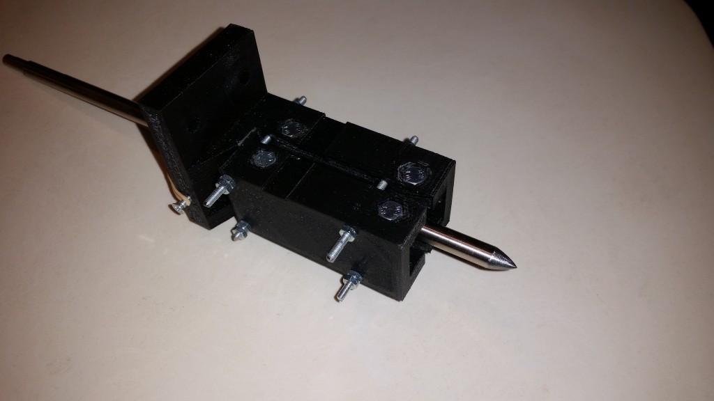
I made myself a holder for a steel rod that could scrape off excessive marker from the copper clad board. I used Sketchup to draw the 3D-model for the holder:
You can download the 3D model from Sketchup 3D Warehouse. I exported the parts as STL-files. I used meter as the unit in Sketchup and mm as unit for the 3D printer (.stl-file). So one meter in Sketchup is one millimeter in real life. 3D-printable file: 3D_Printer_PCB_maker_steel_rod_holder_for_K8200_all.stl
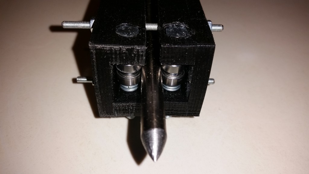
This design will only work with the K8200 printer from Velleman. If you want to try this on other printers, you’ll have to redesign the rod-holder. I used some M3 and M5 bolts to assemble the rod-holder. The rod itself is rolling on 8 ball bearings. The ball bearings are 10mm outer diameter and 5 mm inner diameter. At the top I assembled a ring attached with a rubber band so the rod will be pressed down to the print bed with a soft touch. This will compensate for uneven copper clads and print beds.
The steel rod is from an old flat-bed scanner. I filed it down to a sharp point. The pointier, the better.
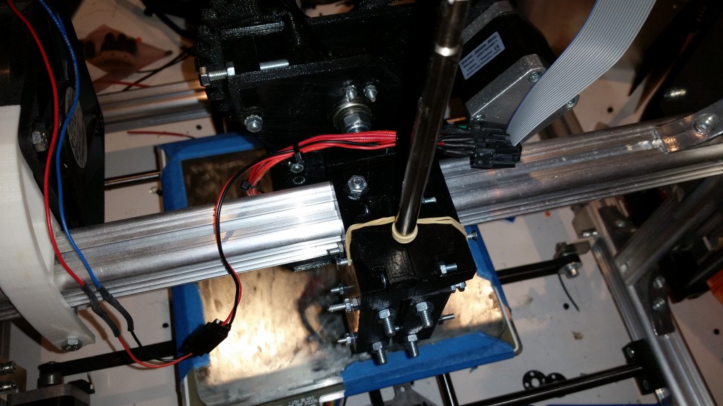
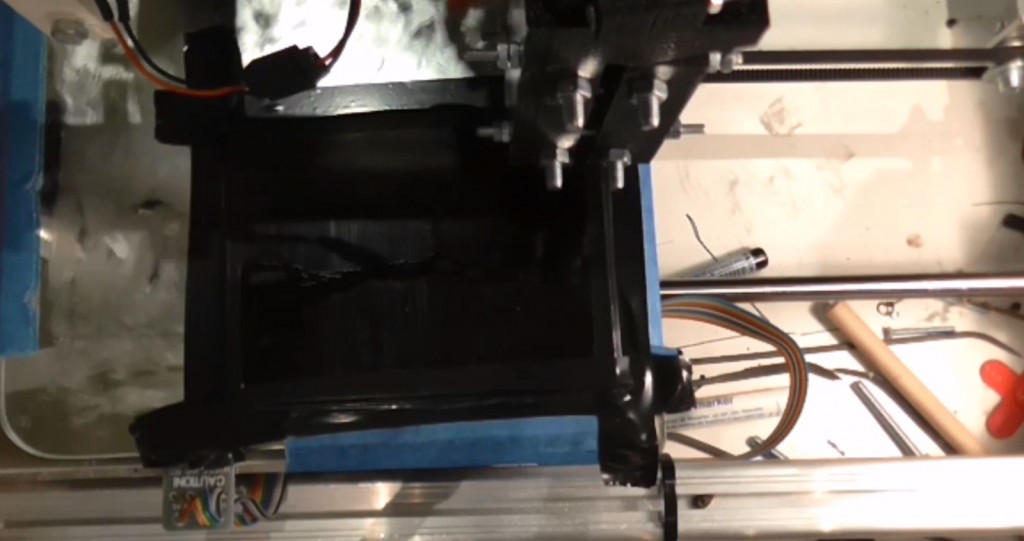
I then mounted it on the printer:
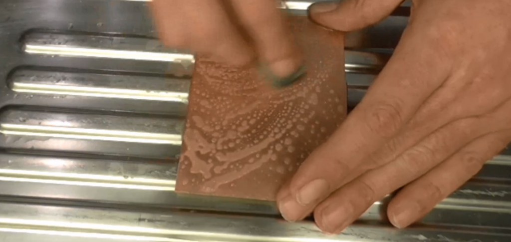
Before I start I clean the copper with steel wool and acetone.
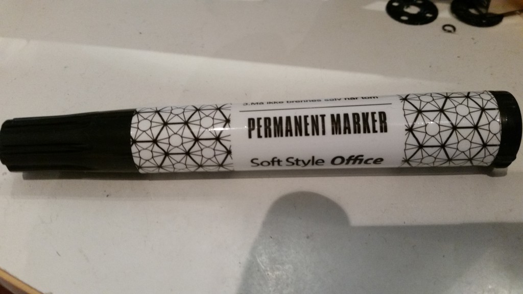
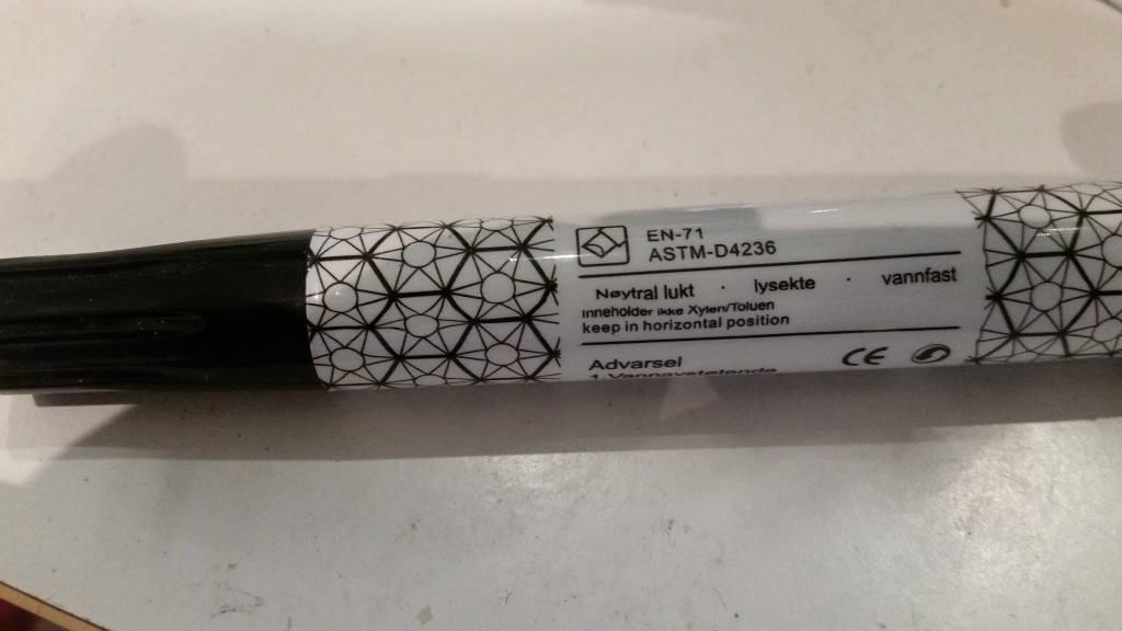
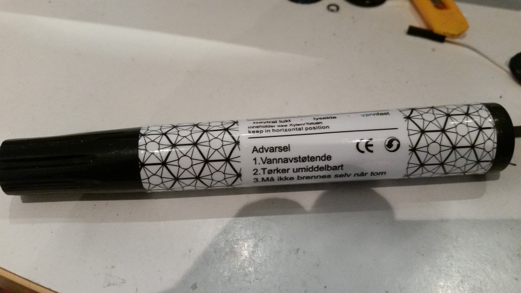
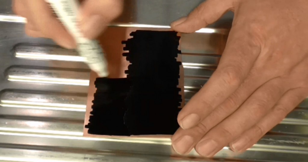
I then covered the copper with black permanent marker. The type of marker will have an effect on the result. You’ll need to experiment with different markers to find one working well. I used one from a norwegian grocery store Rema1000, as shown below:
I then attached the copper board to the printer with som tape.
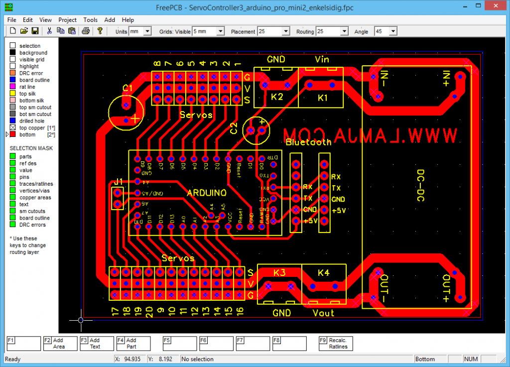
I designed the PCB with FreePCB. It’s a bit outdated, but it’s easy to use, and it’s what I’m used to work with. You might want to use KiCad instead. That is a bit more up to date, and is still under active developement.
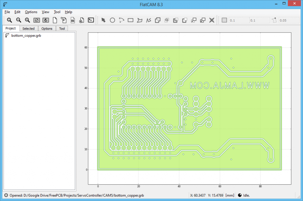
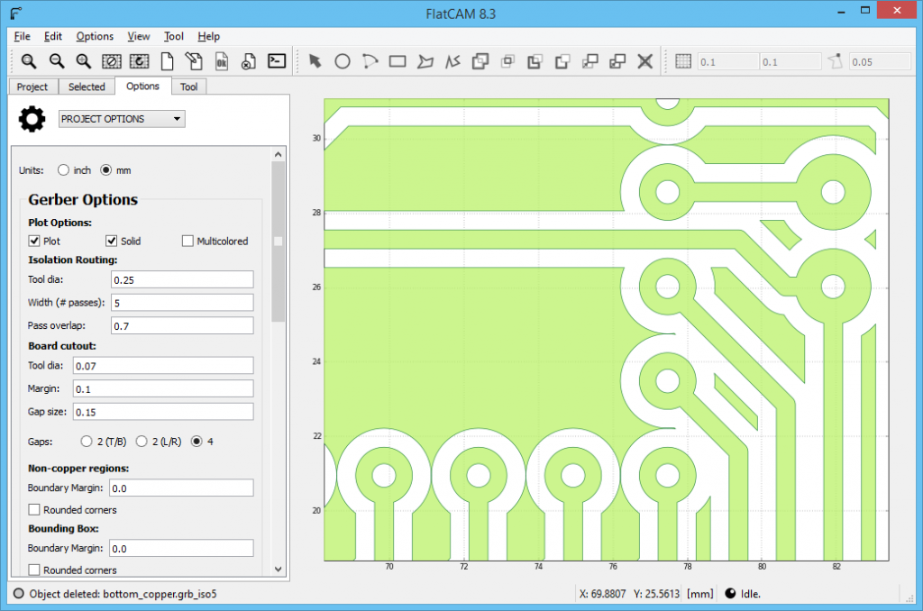
I exported to a Gerber file from FreePCB. Then I have to create the G-code for the printer. I used a great program called FlatCAM. It’s a bit tricky to get used to at start, but it’s really flexible. Import the Gerber file into FlatCAM [File/Open Gerber]. Select the imported file by clicking it:
The Gerber has to be mirrored because this i the bottom layer. Click [Tool/Double Sided PCB Tool]. Select [Y] and [Box] and then click [Mirror Object].
Check that you are working in millimeters. I think most 3D firmware are working in mm, so you’ll need to have G-Code in mm as well:
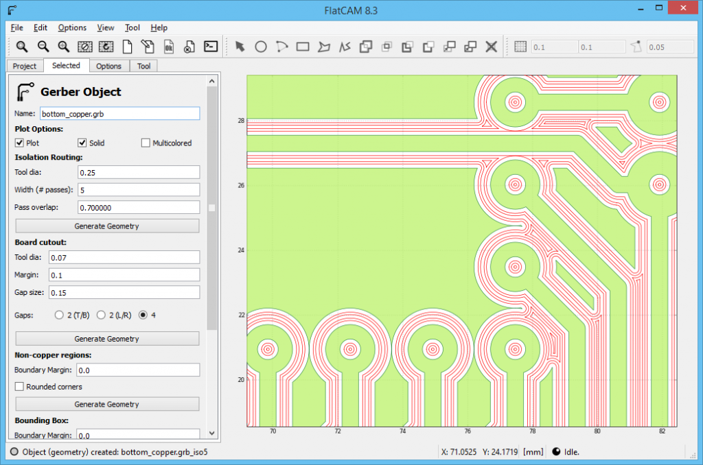
To make the isolation paths, click the [Selected]-tab. Be sure you have selected the gerber-file in the [Project]-tab. Set the [Tool dia], [Width] and the [Pass overlap] as below, and click [Generate Geometry] under [Isolation Routing]. You may need to experiment with these parameters, and test what will fit your printer best.
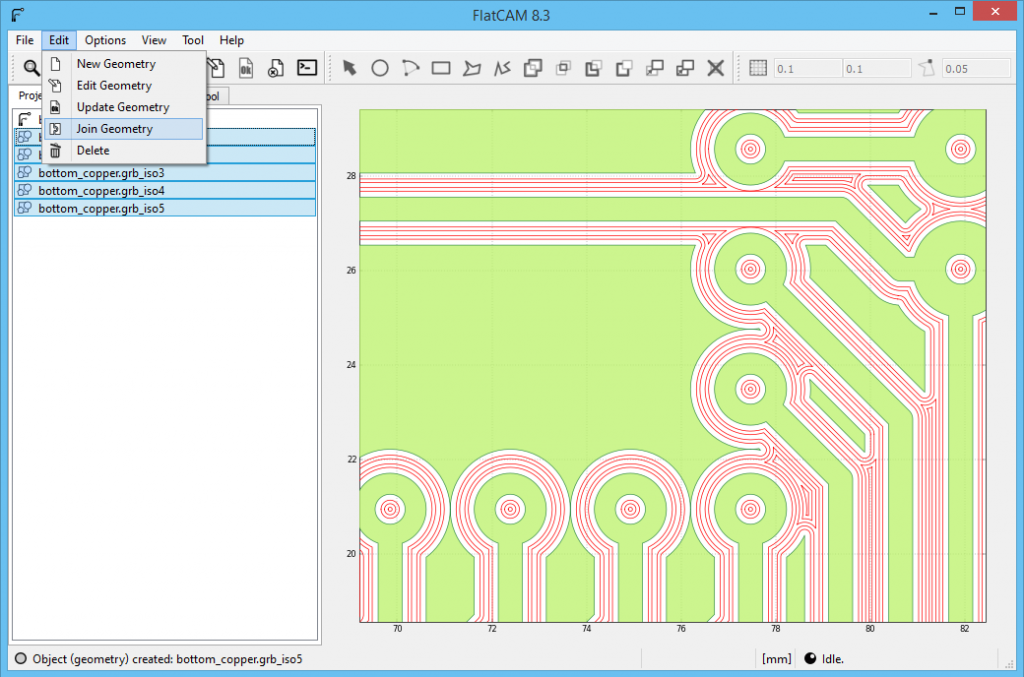
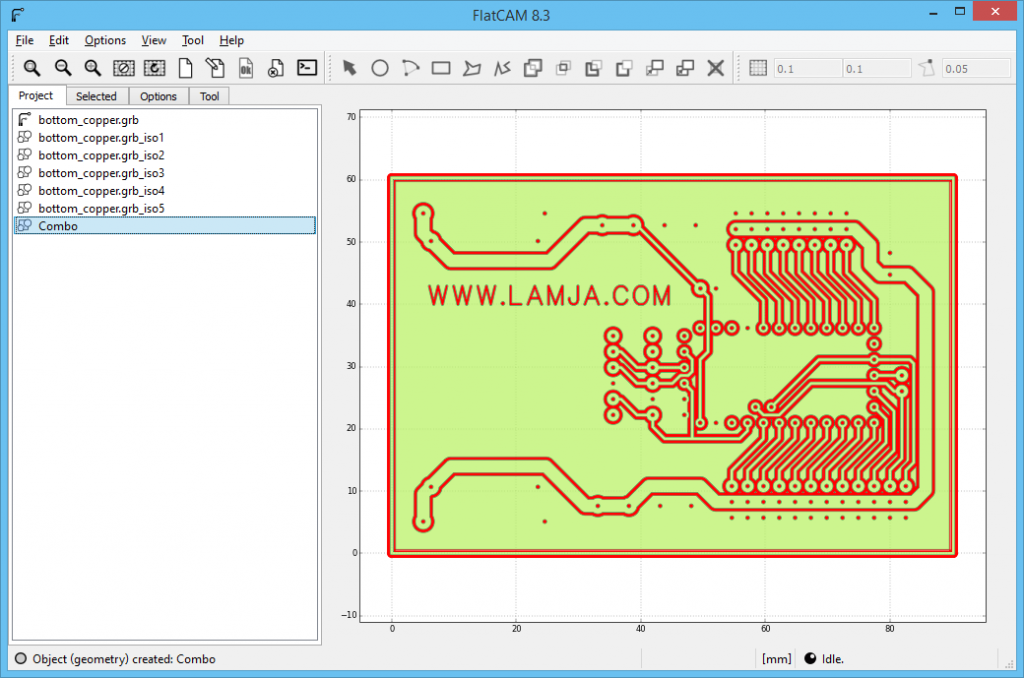
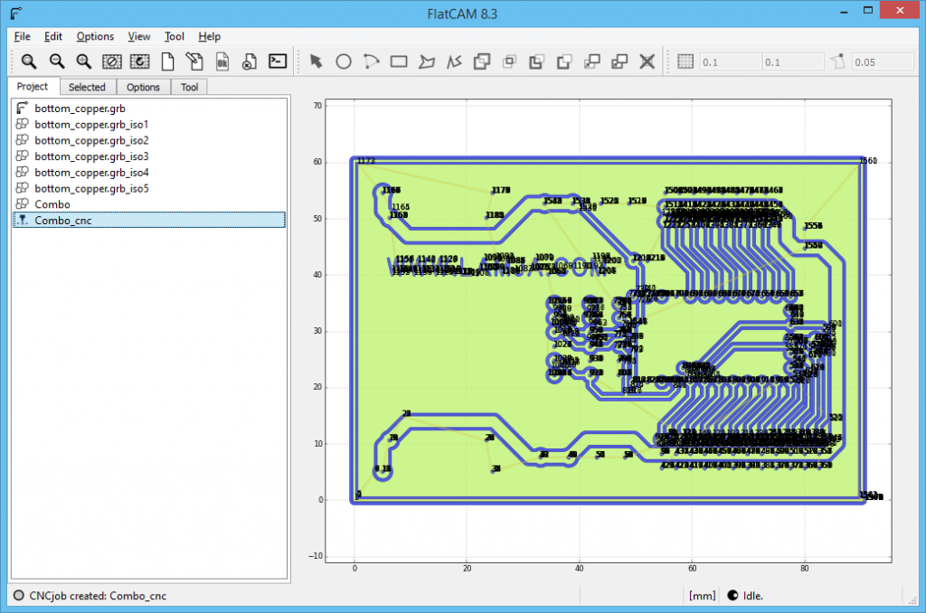
Go back to the [Project]-tab and select all the new geometries created (.iso1-.iso5). Click [Edit/Join Geometry] in the menu.
Select the new Combo-geometry created.
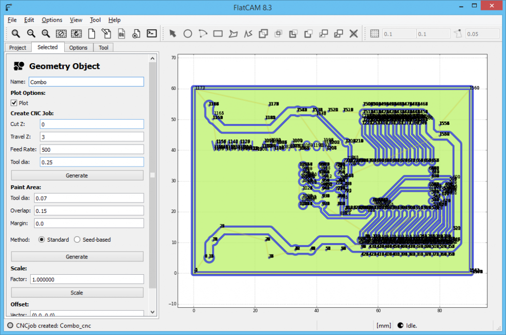
Click the [Selected]-tab. Fill in parameters under [Create CNC Job]. [Cut Z]=0 means that the printer will scrape at Z=0 mm. [Travel]=3 means that the printer will lift 3mm before travel to next scrape-location. You’ll need to adjust the for your printer, and experiment what will be the best for you.
Select the Combo_cnc just created.
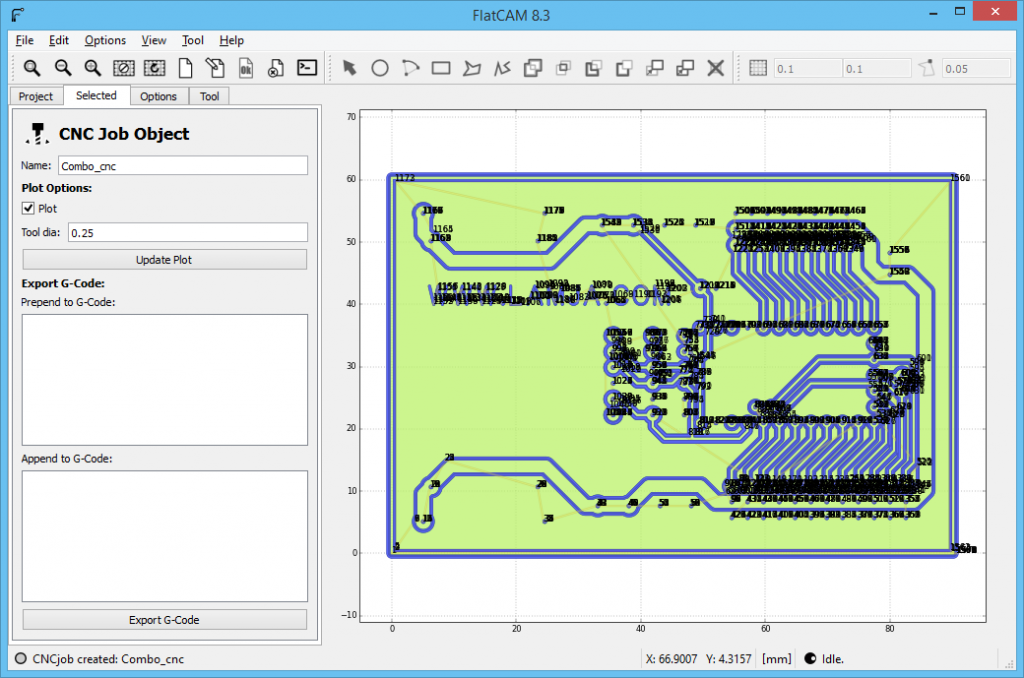
Go to the [Selected]-tab and click [Export G-Code]
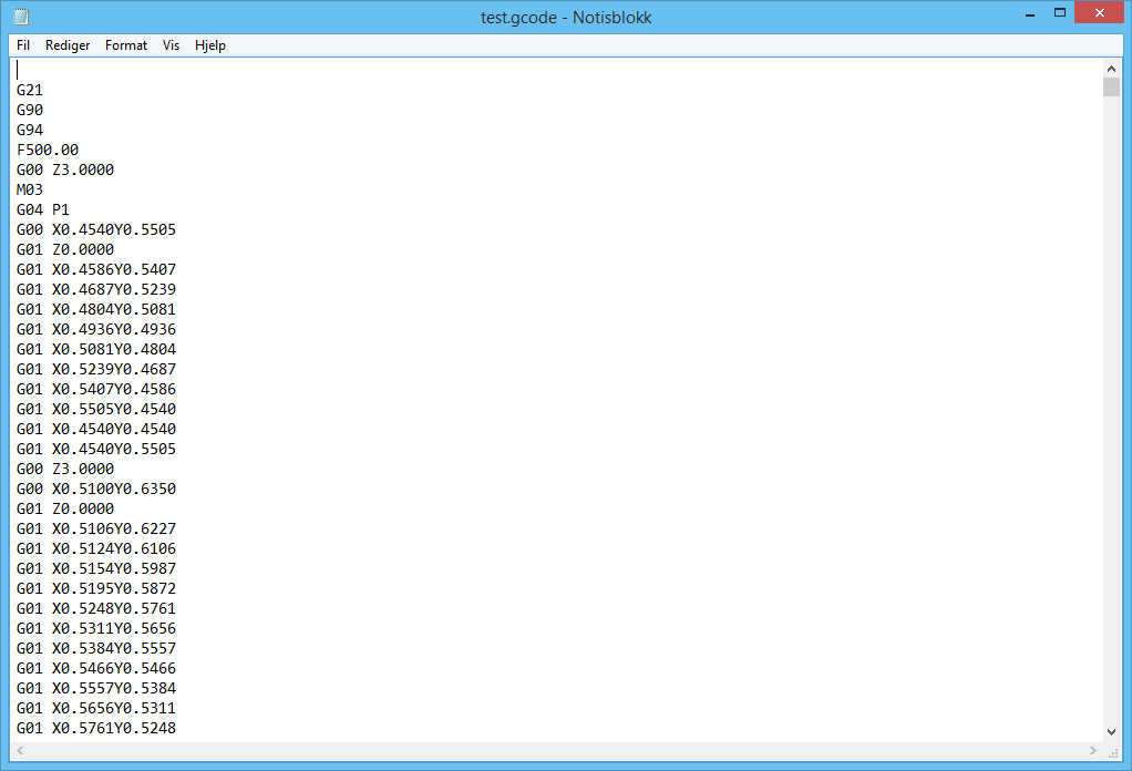
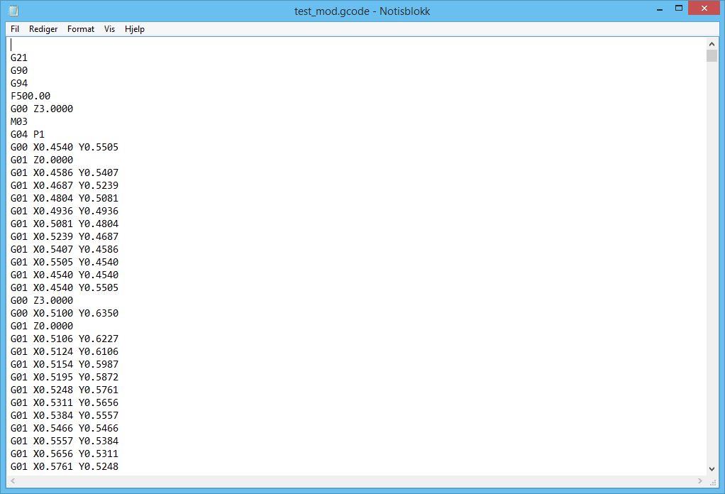
Your G-Code will look something like this:
If you use Marlin-firmware for your printer, you’ll need to change the G-Code a tiny bit. Just replace “Y” with ” Y” so all capital Y will get a space in front of it. Like this:
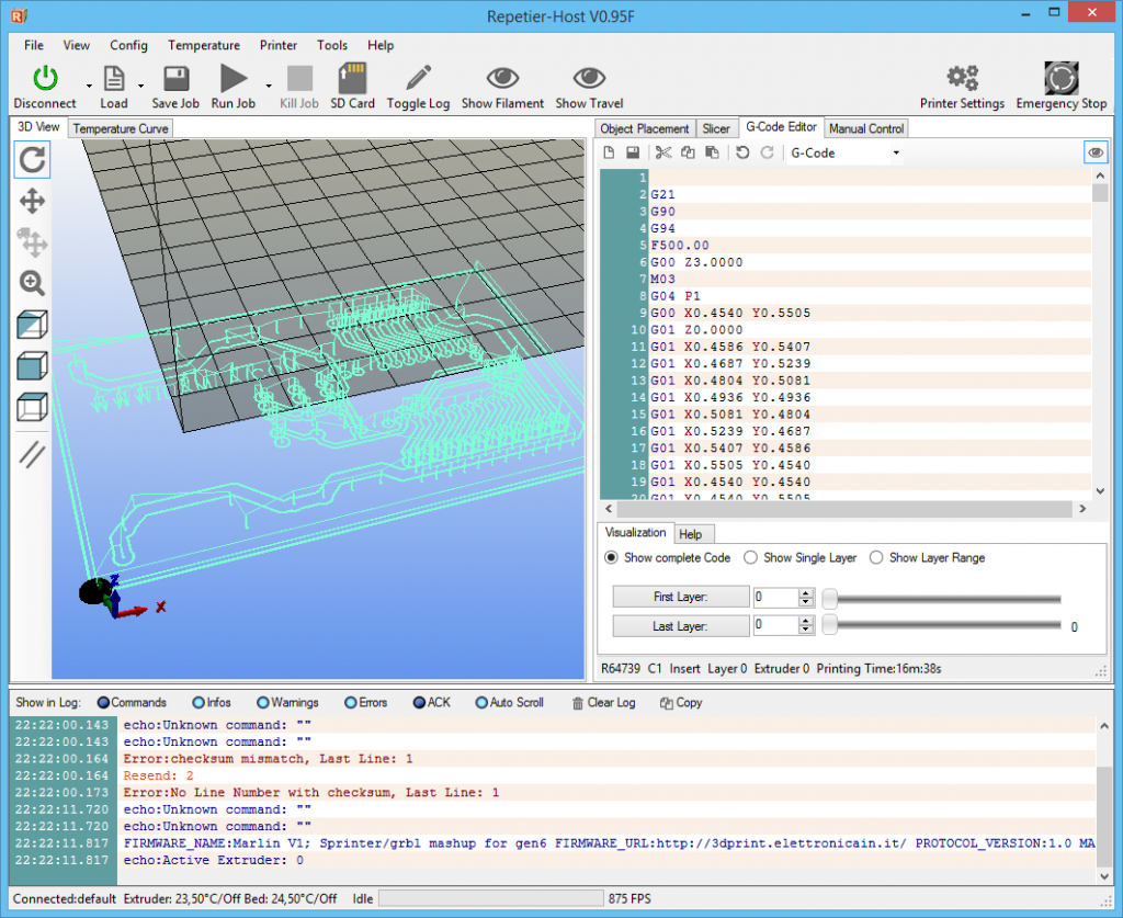
Open your 3D-printer software. In my case I use Repitier Host. Go to the [G-Code Editor] and paste all your new G-Code. If you click [Show Travel], the whole G-Code will be visible as travel. There will be no layers visible since there is no extrusion in the G-Code.
Now, you’ll need to position the metal rod and zero your printer X, Y and Z so that it will fit the copper. Move the tip of the metal rod to the lower left corner of the copper clad board. Ensure the printer will have no trouble travel the whole copper board. Lower the tip so that it touches the copper plate, and the lower it another mm. This will tension the rubber band and give lite pressure to the copper plate. This will be the height for the Z for the scraping part. Remember that the tip will only lift 3mm as we specified in FlatCAM. In this case it will travel just 2mm above the copper board since we went down 1mm below zero. Now you’ll have to zero out the printer X,Y,Z.
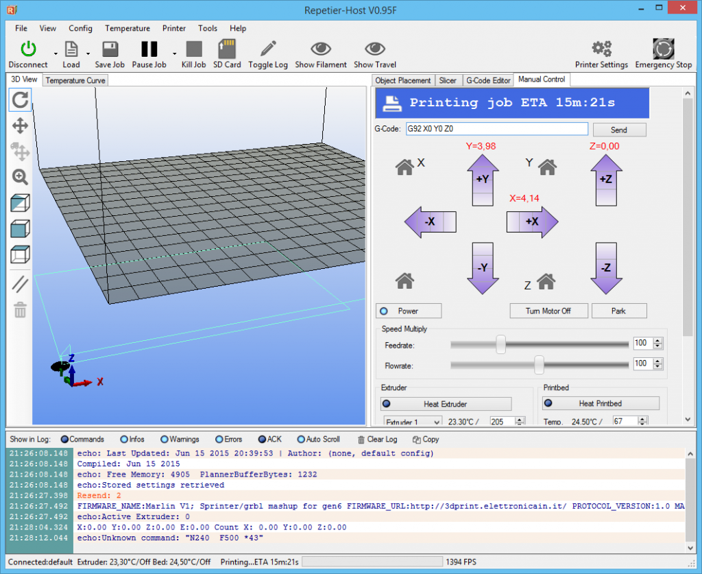
Go to [Manual Control]-tab, and enter these G-Codes:
G92 X0 Y0 Z0
M114
You will have to press [Enter] or [Send] for each line.
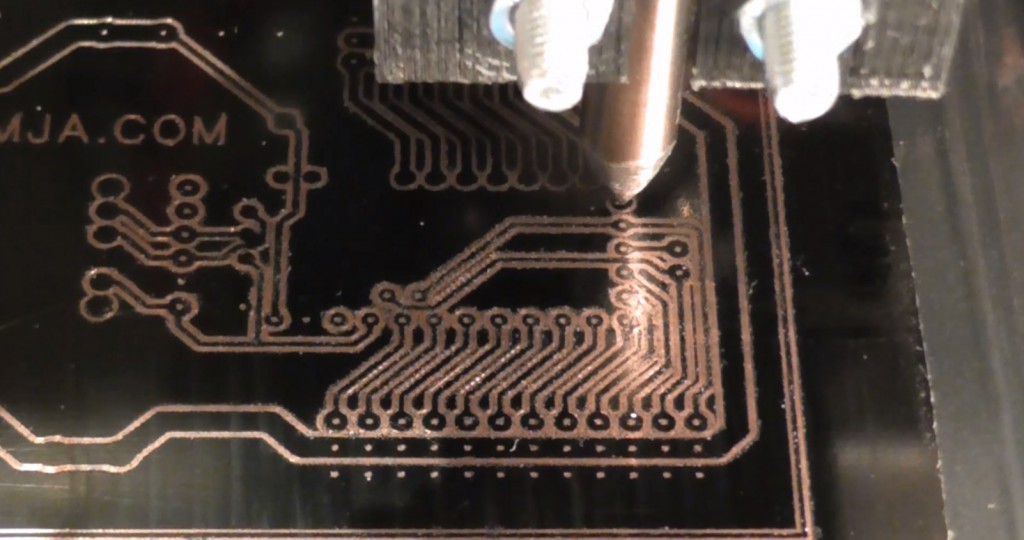
As a precaution, it’s recommended to watch the printer starting and ensure it will not crash or travel beyond the limits. I used the power for the printer to stop all movements if I saw something strange happening. That might save your printer for a mishap. The 3D-printer in work:
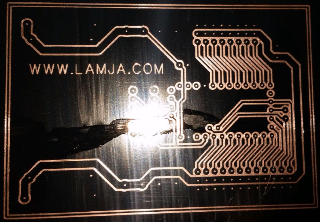
When finished the copper will look something like this:
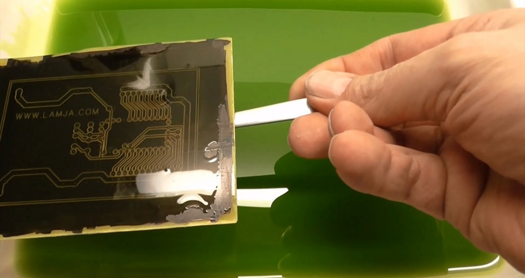
Then I used some ferric chloride to etch away the exposed copper:
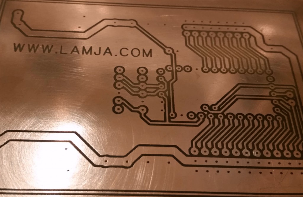
And then I have the finished resulting PCB ready to be drilled:
Feel free to comment, like and share.



Fantastic innovative thinking! So simple, straightforward and accurate. I am going to try this. Would a thin layer of enamel spray paint work? Alternatively dip the board in a thinned down tin of paint? Your idea of the elastic band is a super idea. I want to use this on my CNC when testing out a new cut. This can later be refined to a tensioned spring.
Hi. Thanks. I don’t know about spray paint, but CA-glue and glue stick did not work for me.
Regards
Arvid
Fantastic idea.
I’m working through making this work with my Duplicator 4 (Makerbot clone). I’m using DesignSpark for my PCB layout but I’m having one small issue in that my Gerber file does not have the holes shown in the pads. I suspect that it is something to do with DesignSpark but there is a problem posting on their forum at the moment and I’m awaiting a response from the Support people. I can output a drill file and have successfully got all of the holes showing in Flatcam. If I use the Join Geometry option on the Gerber and drill files then I can’t produce the isolation. I’m wondering if there is a way that you know of to do this?
For anybody else reading this I’ve documented how to make the Gcode work with a Duplicator / Makerbot
I’ve also found that the Outputted Gcode can not be used ‘as is’ with my machine.
There are 4 codes that are not supported. M03, M05, G94 and anything starting with F on it’s own line.
I’ve found that by using Notepad++ I can easily edit the file and add the speed to the end of each line.
What I did first was to go to View > Show Symbol > Show All Characters. You will the see the CR and LF showing the end of each line. Notice there is a CR LF at the start of the file. DO NOT DELETE IT.
Then delete the G94, Fxxx.xx, M03 lines at the start of the Gcode, the delete the M05 line at the end of the file.
Next I used the Find and Replace tool (Ctrl-H) to add my speed to the end of each line.
On the Replace Tab click the Regular Expression radio button at the bottom of the box under Search Mode. In the Find what : box enter $ in the Replace with : box enter [Space]Fxxx.xx (where xxx.xx is your desired speed, I’m happy with F1200.00) and click Replace All. NOTE make sure to put a space in front of the Fxxx.xx. It will take a few moments / minutes depending on how fast your PC is.
You will notice the first line has now become ” Fxxx.xxCRLF”. Delete the ” Fxxx.xx” and leave the CRLF
Also the next two lines G21 and G90 will need the “Fxxx.xx” removing as will G04 line which should be the 5th line.
Save the file with a different filename so as to keep the original.
I’ve found you can subsequently experiment by replacing the “Fxxx.xx” with a different value for different speeds. Make sure you search for “Fxxx.xx” and not just the “xxx.xx” when you do this.
I then used the ReplicatorG program that came with my machine to load the Gcode and the Manual Controls to position the head and pressed build.
Hi. No cant generate isolation from drill file either. If you use “Mill holes” on the drill-file, it produces one pass “isolation” for the holes, and you may create more of them with different size mills. Then you got a lot of different kind of isolation for the holes that can be combined.
In FreePCB, you have to select “Generate Pilote Holes” for the Gerber-generation. I guess there will be a setting for this in Designspark as well.
Regards
Arvid
Thanks a lot for sharing this Arvid. Also thanks Neil for taking the time to share how to make it work with the Duplicator … I look forward to trying this.
What solution did you come up with for mounting the scraping stylus Neil ?
The issue with DesignSpark has been solved and the holes are appearing in the Gerber file as verified using GC-Prevue but still aren’t there in FlatCAM.
I’ve put a message on the FlatCAM discussion group to see if they can come up with something.
– Neil
arvid –
I’ve worked out how to do the drill holes from a drill file produced by DesignSpark.
Munt –
I’ve found that my present solution for the stylus is not working particularly well. I think it’s because the way that I was going to mount it wouldn’t work so I had to do some quick and dirty modifications but that meant that the overall length was quite long which caused a lot of flex in the guide bars as the stylus holder had to mounted under the nozzle carrier. I noticed on arvid’s video that the stylus is stationary and the table moves in X -Y. This, I think, is a lot more stable setup.
I also had a problem in that I obtained a piece of 5mm Silver Steel rod to make the stylus, £4.49 for a 350mm length on Ebay, cut off about 60mm and held it in my cordless drill and sharpened it to a point. I hardened it (loads of tutorials on internet on how to do this although I know how to do it anyway) and used it. The problem was I took arvid’s advice on “the pointer the better” because at the moment my point is too pointy. I’ve used my USB microscope and measured my point at 0.05mm which it to small resulting in the scraping not joining up, but that’s easy to cure, a couple of runs across a sharpening stone should sort that out.
I’m working on a better way to mount the stylus as close as possible to the guides as to reduce the flexure as much as possible which I hope to have completed later today / tomorrow. When I’ve come up with the solution I’ll post back hopefully with some pictures.
– Neil
I’m working on version
arvid,
Do you know where I can obtain the marker that you are using as I’m having trouble locating something that works? I’ve tried a Sharpie as that’s what I already had laying around but even after warming with a hair dryer it doesn’t seem to go quite hard enough and feels slightly ‘greasy’ if you rub over it with your finger. This transposes into it building up on the point eventually and causing it to move over the surface.
If I can’t get the one you used do you know of which ones didn’t work so as I can weed out the alternatives.
Hi. I bought this from Rema1000 in Norway. One of the biggest grocery store here. I will add some photos of it, but it has some norwegian printed text.
how can i export .Gerber file from eaglecad?
Hi Manuel,
What you have to do is the following:
Open your board project in Eagle and then do the following:
1. Click on ‘File’ -> ‘CAM Processor’ -> ‘Open’ -> ‘Job’ -> and choose:
a) gerb274x.cam to create gerber files
b) excellon.cam to create drill file
2. Click on ‘Process Job’ and you will find the file in your project directory.
Your gerber files are ready for FlatCAM.
Enjoy – Seb.
Hi! Seb,
The excellon and the gerber file is not getting mapped on top of eac other.
Can you please explain in details how you made it working.
-thanks
Rajib
Hi Rajib,
I am using free gerber viewer gerber to correct the eagle drill file (this is the file with drd extension). Just open the drd file in gerbv and save it. After this it will open in FlatCAM with proper scaling. It works OK with drd files from Eagle 6.5, but not from 7.x.
Gerbv can be downloaded from here: http://sourceforge.net/projects/gerbv/files/gerbv/gerbv-2.6.1/
I tried this method and it works pretty good. But why not replace the metal rod with a permanent fine liner and write all the PCB lines on the copper. You can do more passes to get a good line if necessary. Should be good enough for pcb’s with not to thin lines. I have tried this an it works but I need a gcode generator who is drawing the actual inner PCB traces and not around them like for this scratch method. Any suggestions to achieve this?
I was inspired by this project and as I thought about it (whilst hunting for all the components I need) I thought that drawing the circuit should be enough without all the scribing. You can get a point that is 0.3mm from the ‘Sharpie’ range but someone had said that that brand was problematic. What brand of pen did you use?
Can’t you export the circuit diagram as a bitmap and convert that to gcode?
I see there are lots of options http://replicat.org/generators
Hi. I did try to draw the circuit with a really fine sharpie, but it did not turn out good. Bitmap to G-code is not easy. If there is any programs doing that, I will guess it’s a mess, or you’ll have to do a lot of manual adjustment. The brand of sharpie I used is explained in the article.
Regards
Arvid
how wide the resulting track using this method ?
The thinnest traces are 20 mils on this board.
That is awesome!!! The great work was done. Thanks a lot.
Hi. Im using Proteus ARES for designing the pcb, and it’s gerber don’t have the pilot holes like FreePCB. Ares give me the board, and the Excellon file.
I open both in FlatCAM, and the board drawing is good, but how will I generate the path for drawing the hole instead of drilling it?
Thanks
Hi. As I mentioned in previous comment : “If you use “Mill holes” on the drill-file, it produces one pass “isolation” for the holes, and you may create more of them with different size mills. Then you got a lot of different kind of isolation for the holes that can be combined.”
Then you can combine that with the rest of the work.
Regards Arvid
Hi,
Great idea. One quick question if I may. Did you leave your extruder mounted or did you remove it? I have a MakerFarm Prusa 10″ i3v that I want to do this on. Hoping I don’t have to remove the extruder and just modify your steel rod holder to mount to my printer. Thanks for your input.
Will.
Hi. I did left it on. The rod was lower that the extruder. I did make sure not to home the Z-axis, as this would have driver the rod crashing into the print bed.
Regards
Arvid
I just wanted to inform you that your work has helped me a lot. I find it a lot easier to use spray paint instead of permanent marker for the resist. At first I have tried ordinary black spray paint for cars because these are usually quite thin. However the dried paint is also quite brittle and although it can be easily scraped off, the edges will look a little frazzled. Finally I used spray primer and this turned out just perfect because it is softer when dried.
Before reading your post, I originally intended to print the traces with 3D print material (tried PLA and ABS), but I couldn’t get the material sticking onto the board even with high bed temperatures. Now having seen the precision of your method I also highly doubt that the additive print would have been accurate enough (1.75 mm filament).
Instead of using your design files, I have decided to design my own print head for the scraper because I have a special printer (CTC dual extrusion). In my case I have used a broken 9mm titan drill as the scraping tool. I have designed the tool casing so that the modified drill can slide up and down inside the hole in the ABS material. Equipped with a small steel spring the friction of the rod is still low enough to be movable. However it was a lot of rework (like smudging around with ABS in acetone etc.) to get the tolerances of this slider bearing right while keeping friction low. If I ever build this again, I will use linear ball bearings instead (like the ones used in the other axes).
Most importantly, I would have never found FlatCam without your hint, let alone having motivation to try it out for this purpose. When you are doing something innovative, it can be a hassle to sort out the many approaches that do NOT work with reasonable effort. And if you finally delve into MAKING things work, you often end up noticing that you have reinvented the wheel. 🙂
So thank you very much for sharing your method.
Regards,
Oliver
Thank you for the kind words.
Regards
Arvid
Super idea!
I think I would use a linear bearing from EBay or Aliexpress to guide the 8mm pin up and down movement instead of the ball bearing assembly.
Best regards,
Bert
I have found that that machine marking ink (gentian violet + alcohol + shellac) works exceedingly well. The lines come out very fine with no raggedness. If you need to cross over lines, the intersection is perfect. I bought my marking ink in a spray can. I would be interested if anyone else has found this method useful.
With a sharp point, the marking lines can be made within 0.1 mm. Well within the precision of any cnc or 3D printer. I think that this can be developed to create some really high precision work for SMDs etc.
Cheers,
Brian
Great idea, and excellent result. Thank you for taking the time to write it up!
If I can find the time, I’ll make a similar rod holder for Printrbot (Plus) and experiment with using Dykem instead of a permanent marker.
How amazing 😀
your technique is the same as the technique we are using in our product Projecta .. which will be on kickstarter so soon ^_^
Join us:
Hi,
I didn’t understand how it works exactly, I am missing something.
Once the printer is done, you have the copper pattern exposed and all the other area is coverd with marker. Than, you etch the sample meaning the copper pcb pattern is etched away. It seems to me like the opposite thing to do. It’s like you printed the PCB’s negative.
I would really appreciate an explanation.
Thanks.
The printer is removing the marker where I don’t want copper. I use FlatCam as isolation-reouting, meaning it will draw graphics inbetween the copper patterns.
At the moment I am building the K8200, and I intend to use your method for making PCB’s. I am just wondering, do you have a special reason to use the 8 ball bearings? I was thinking of moving the rod inside 2 linear bearings, just like the ones being used in the printer itself, which will of course mean a modification of the print head.
I just used what I had at hand. As long there is no play in the rod and it moves freely, it would work fine.
Very nice method!,
I tried it and create the gcode file but this file is visible only in the Repetier program, my printer doesn’t have serial port so I can’t connect it to Repetier, I use Simplify3D or Voxelizer but the Gcode generated isn’t visible with these programs.
Have some idea why, or some suggestions?
Many thanks
Hello there.
I am building a similar tool form my FABTotum 3d printer. head is ready and now I need to export holes as MILL as Robert asked above. I am newbie, I tried but I cant’ find a way to do it. Any help?
Thank you. Great job Arvid!
Thanks from Brazil for your VERY USEFUL project.
Hi Arvid… I’m using freepcb and have created the bottom copper.grb. When I import this into FlatCAM, the pads for components have sections of the pad cut out so it allows copper to be inside the pad! I found that removing the X inside the pad, which is the net name, gave me pads that are perfect donuts showing the clearance needed between the pad and the ground. Now I can’t get tracks to appear in FlatCAM. If I use pin connect, I need the net name. Now I’m back to the same problem where the pad is connected to ground! I tried start stub without any success. How do I get the traces down and show up in FlatCAM? Thanks in advance, for a great idea and all your work.
I solved my problem. It was necessary to assign a Net name to the traces. Once the X is gone from the holes, the traces showed up in FlatCAM and Viewmate…
This was the most difficult sequence for me so passing it on incase others have the same problem. Thanks again Arvid for a great idea.
Great.
Hi. Not sure what you are trying to do. Do you have a copper area that is filled i Freepcb?
At first glance I found it to be a stupid idea with an Edding marker pen and a 3D-printer to etch a board. But after viewing the video I can only say: GREAT IDEA!
I would have never thought of it by myself, although I’m an Electronics Engineer.
Simply Super!!!!
This works great. I have converted a 3d printer with a broken print head to this design.
At first I tried to just zip tie an auto punch to the print head. That didn’t work because of the slack/play in the punch’s needle. I thought about some improvements to the punch but I didn’t feel they would fix it enough.
Then I purchased 4 linear bearing and 8mm rod from Amazon. A friend of mine let me have a chunk of HDPE, that I attached with zip ties to the print head. I only needed two of the bearings stacked right next to each other. The rod was sharpened up in a drill press, using an angle grinder to remove metal.
I use Dykem Layout fluid as an enchant mask. I had to play with the settings some in order to get the pcb to come out looking good. However, they now come out great! All of my nerdy friends are surprised at how well this works.
Give it a try,
Mike
Hi Arvid,
I am using FlatCam and Repetier host, and I follow your example editing the Gcode file exchanging “Y” with ” Y”, the selected unit are in mm., but when I paste the code in the Gcode editor, or load directly the file, I can see somelittle line very short and imposssible to recognize. Can you help me to understand where is the problem ?
Thanks in advance.
Max
Hey, your idea got me all stoked and i’m certainly going to build my own version of this. I will look a lot like this contraption here:
Just imagine instead of the (expensive) laser that there would be just the part of another optical pickup where there are the brass bushings wherein glides the 3mm steel rod. That steel rod has virtuall no slack, so will do a much better job than the automatic center punch that was mentioned above.
[googleapps domain="drive" dir="file/d/19Wm9FTMBA7Pv8JZ542wAG1FNnnJ18U3a/preview" query="" width="640" height="480" /]
I am still waiting for my RAMPS board, when it arrives I will build this. I just hope the puny steppers will be powerful enough to scratch the paint off the copper. If not i will simply build something stronger.
Thanks for the inspiration.
I have used Eagle+Flatcam then a 3d Delta printer. The movement of the rod is OK.
I have tried with two different permanent markers but I am not able to scrap the isolation route from the copper pcb?? Any help would be appreciate
Sharper point maybe. Brush the dust off at the end.