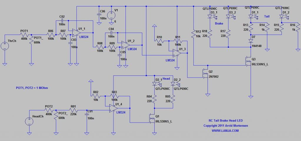
This is a simple way for adding head lights, brake lights and tail light for a RC car. I used a LM324 op-amp to filter the PWM signal from the servo channels. The throttle channel is heavily filtered to get a clean on/off signal for the LED’s when the throttle goes in reverse (brake). A third channel can be used to control the head lights. This signal is not filtered as much as the throttle signal. This cause it to be able to fade from no lights to full lights. This is caused by the 50Hz servo channel signal being used as a PWM for the head LED’s.
The brake lights will only be on when the trhottle is below zero. The tail lights will light up slightly when there is no brake, and be fully on when there is brake. The brake lights will also be on in reverse, but if you adjust the crossing point to be pretty low (almost full reverse/brake), you can reverse the car at low speed without activating the brake lights. Like I’m doing in the video.
Schematics:
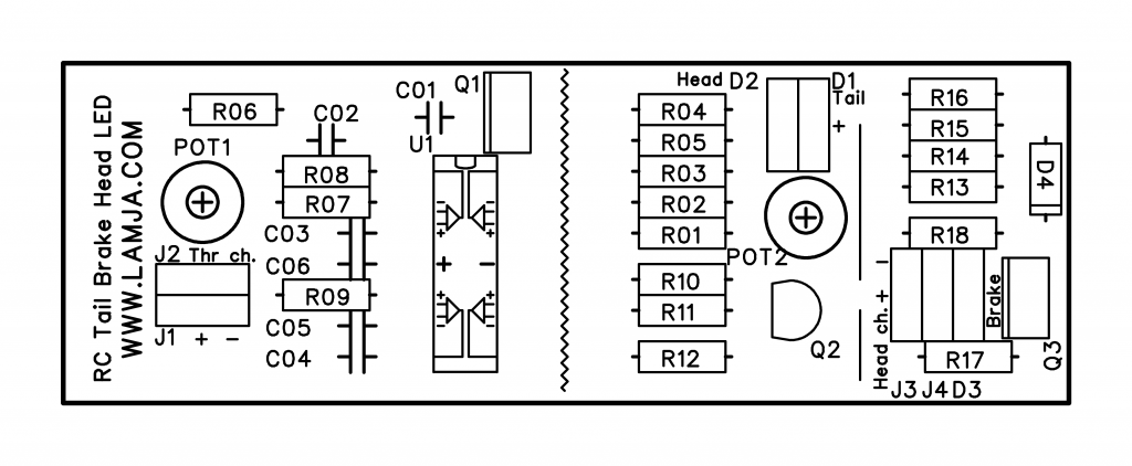
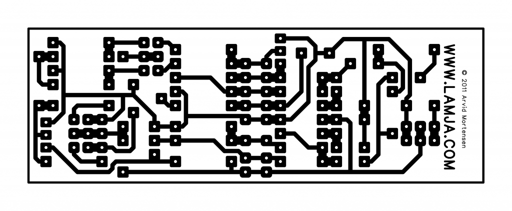
I have made two versions for the PCB-board. One called “split”, and one “no split”. The split version can be cut in half and the folded together with wires connecting the two halves. This way the board will be about 4×3 cm, but twise as thick. The “no split” will be about 7x3cm.
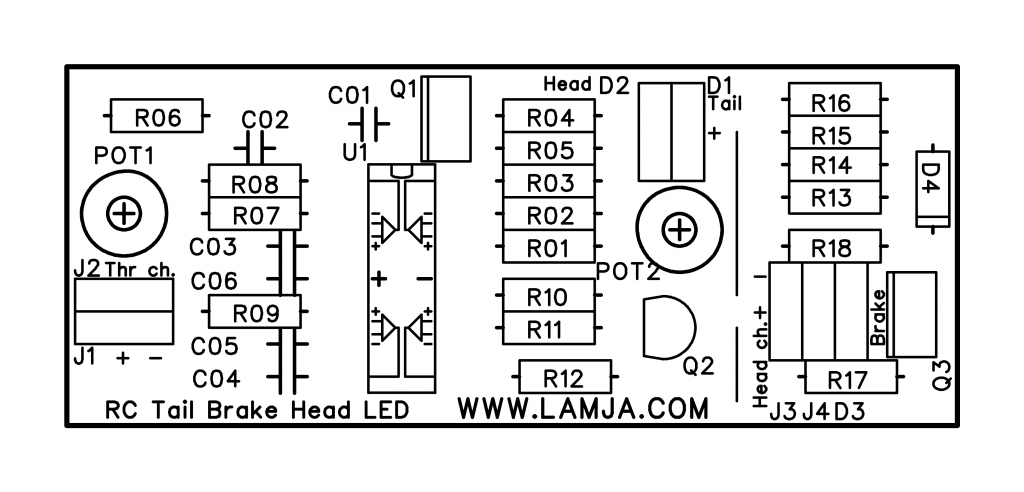
The crossing point for the servo signals is adjusted with POT1 and POT2.
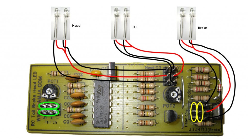
The board is powered from the ESC’s 6V feed for the servos. Take care to connect + and – correctly. I take no responsibility for your use of this. You will do it at you own risk. The servo pins should be Futaba-style, if you connect it the right way. Positive at center. The LED connections also have positive at the middle pin.
You might have to calculate new values for the resistors limiting the current in the LED’s. For my test LED, it had a voltage drop of 2V, and should be able to handle 20mA. The 220 Ohm resistors are scaled for these LED’s.
This design can also be used as a dual RC switch. The brake channel can be inverted by removing the Q2 MOSFET, and the putting a strap in the two upper pins. The ones that is connected to R10 and R11.
For the head channel, you can get a cleaner on/off state by increasing C01. This will decrease the fading limits. Lowering this cap will increase the fading limits.
If you want less light for the tail light when the brake is off, increase R14 and R16 from 1 kOhm to 2.2 kOhm or even higher for less light.
Connections:
Take care to connect + and – correctly for the servo channels.
Split version PCB board layout:
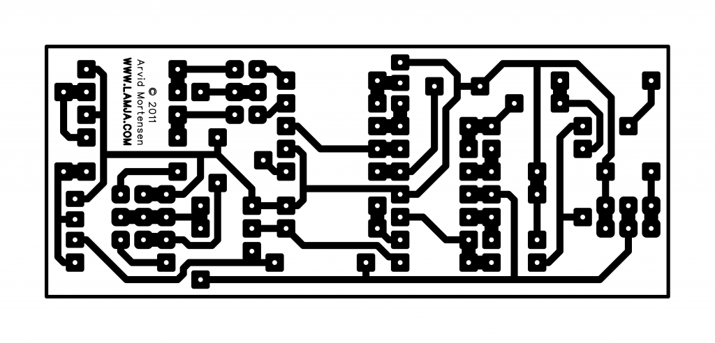
No split version PCB board layout:
Files, including part list and 1200 dpi PCB images:
http://www.lamja.com/blogfiles/RC_Tail_Brake_Head_LED_Partlist.txt
http://www.lamja.com/blogfiles/RC_Tail_Brake_Head_LED_LTSpice.asc
http://www.lamja.com/blogfiles/RC_Tail_Brake_Head_LED_No_Split_BottomCopper.png
http://www.lamja.com/blogfiles/RC_Tail_Brake_Head_LED_No_Split_BottomCopperMirror.png
http://www.lamja.com/blogfiles/RC_Tail_Brake_Head_LED_No_Split_TopSilk.png
http://www.lamja.com/blogfiles/RC_Tail_Brake_Head_LED_No_Split_TopSilkMirror.png
http://www.lamja.com/blogfiles/RC_Tail_Brake_Head_LED_Split_BottomCopper.png
http://www.lamja.com/blogfiles/RC_Tail_Brake_Head_LED_Split_BottomCopperMirror.png
http://www.lamja.com/blogfiles/RC_Tail_Brake_Head_LED_Split_TopSilk.png
http://www.lamja.com/blogfiles/RC_Tail_Brake_Head_LED_Split_TopSilkMirror.png
Feel free to leave comments 🙂



How can I buy this board already assembled?
I want to hook up led lights on RC truck with circuit board.
How do I attach another board?
Do you sell this board assembled?
Hi.
No I don’t sell this. Use the design at your own risk.
hi im trying to build this where do i get the basic pcb board or is it up to me to find it if not where did you get it or did u custom design it, im new to this stuff so excuse and stupid questions 🙂 thanks in advance-eric