This is a project i did a while ago. I made one for my self and two as gifts. I decided to crack open the one I had left, to get some photos and video of the inside. I also did’t remember how I connected the pins to the ATMGEGA 328P. It uses two standard hobby servos, a home made ATMEGA 328P PCB-Board and a MOSFET to turn the power to the servos off in sleep mode. The switch is connected from an input pin trough a 470 Ohm resistor trough the switch and to ground. This will set the input pin to low when the switch is closed. I then use a interrupt to wake the microprocessor.
The boxes in action:
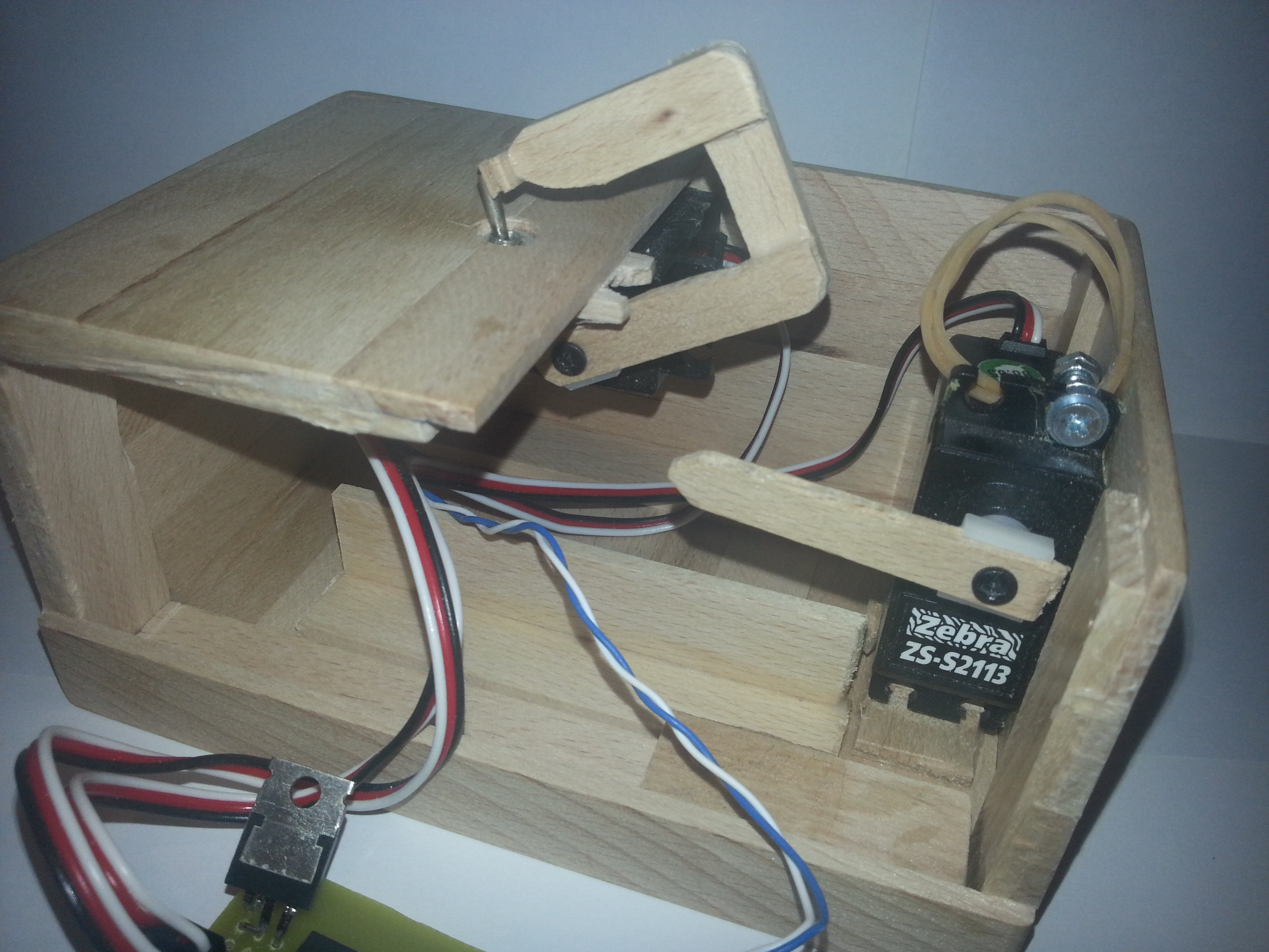
Inside a box:
The PCB that I made has two power inputs. One +5V for the microcontroller, and one +6V for the servos. In this box I use 4 x 1,5V batteries for power. This gets the +6V connected. To get +5V, I connected a diode from +6V to +5V. The voltage drop over the diode is 0.7V, and I then got +5.3V for the microcontroller. This seems to work OK. The switch is connected to S15 (pin 2 on Arduino). The servo for the lid is connected to S05 (pin 12 on the Arduino). The servo for the switch is connected to S06 (pin 13 on the Arduino). MOSFET is conntrolled from Arduino pin 8 (Thats why S01 is missing on the PCB). The ATMGA 328P is programmed on an Arduino. The MOSFET on the picture below is not in the same place as the new version of the PCB.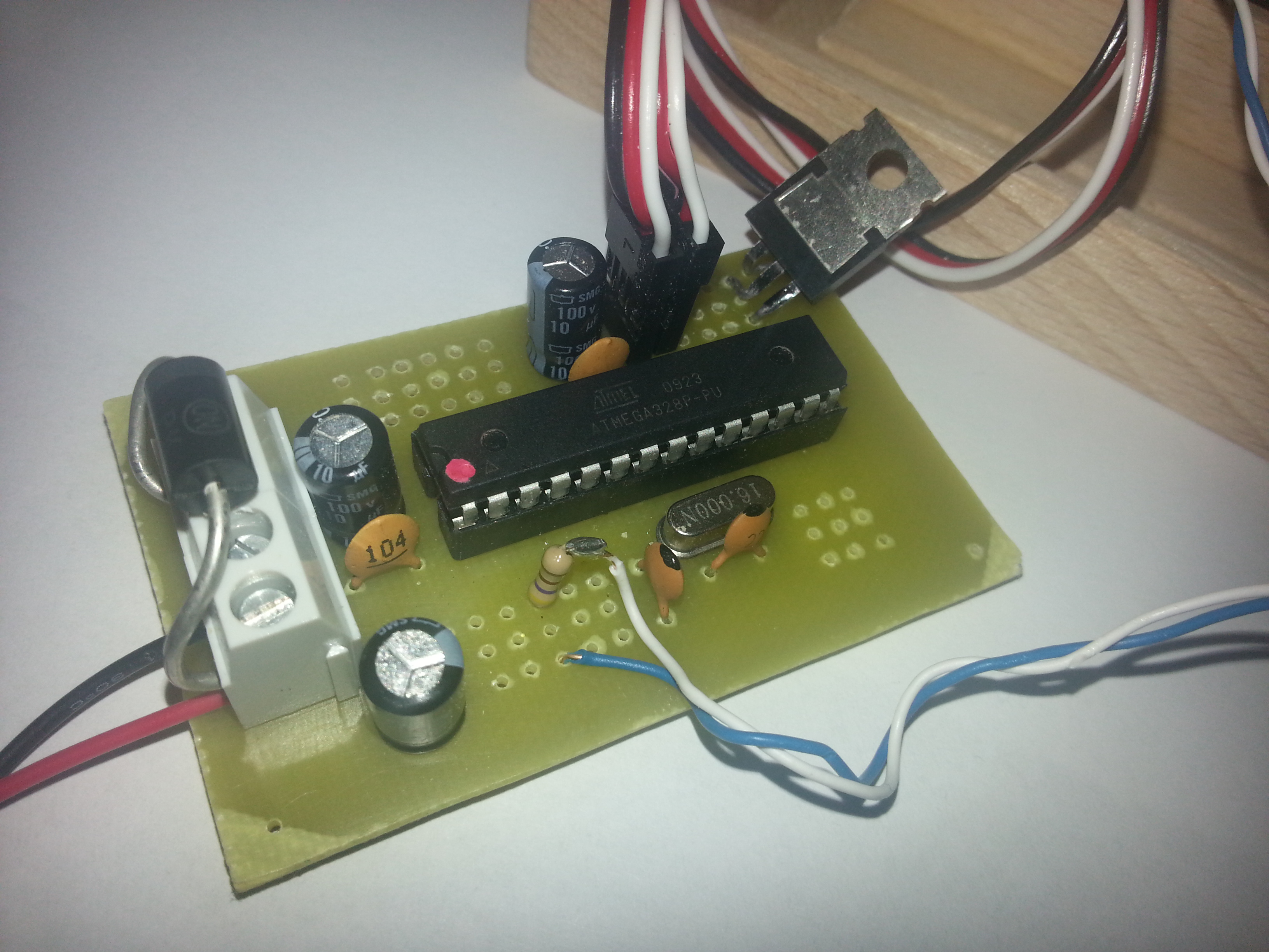
The contruction was a bit tricky. One servo turns off the switch, and the other open the lid.
The PCB board fits the wall at the one side: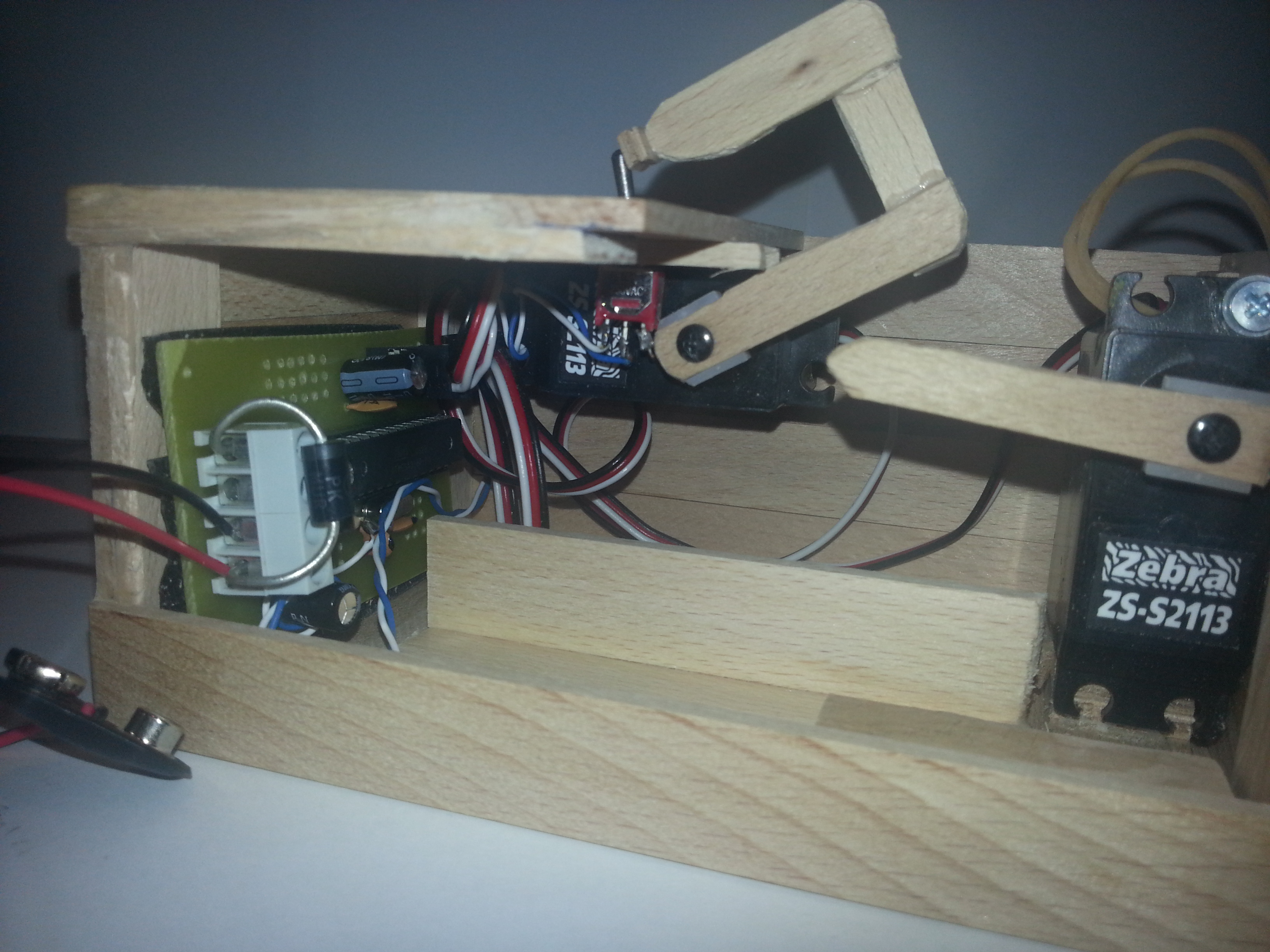
And the the batteries at the bottom: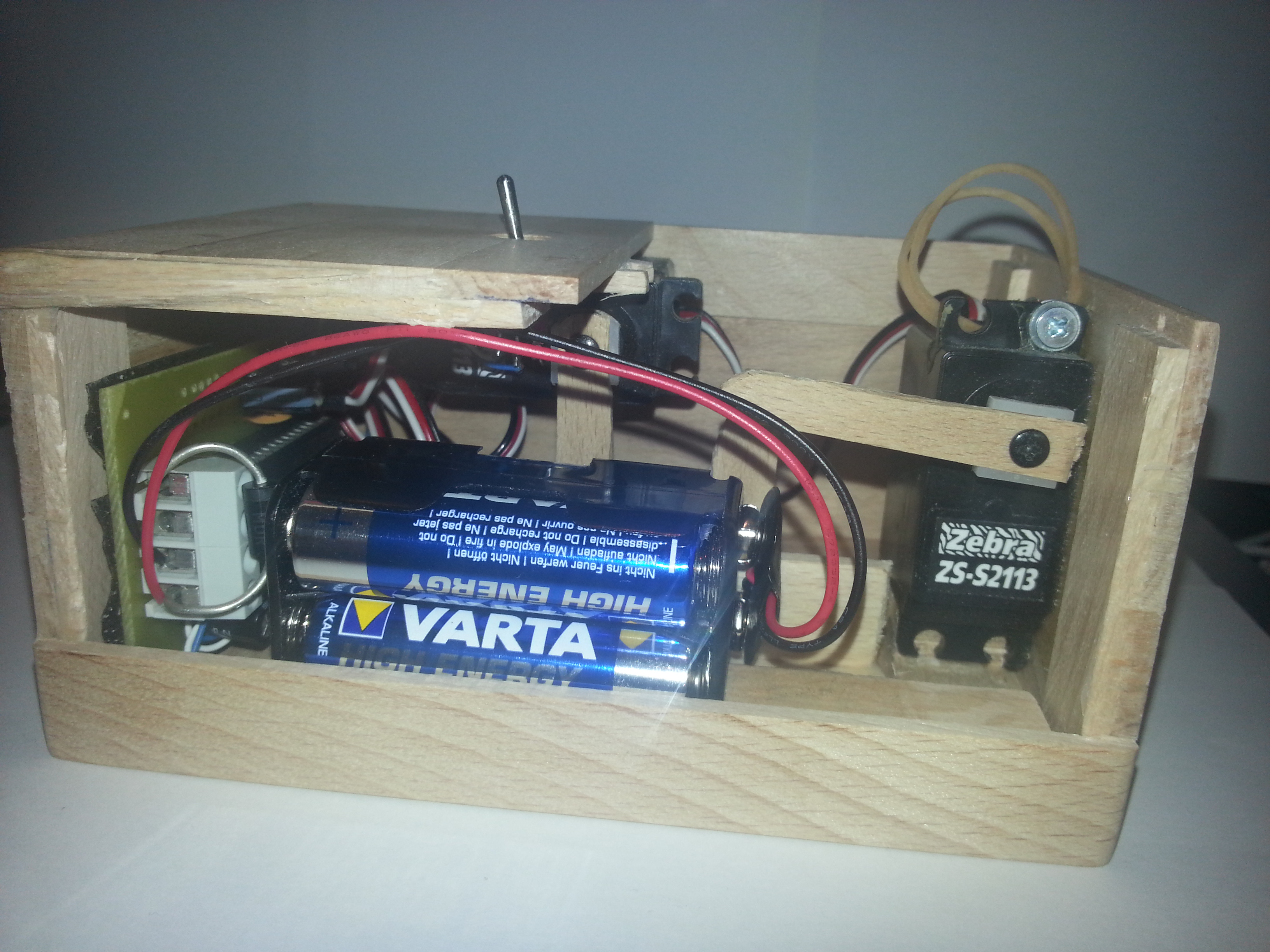
The lid uses two nails to allign the edge to the box.
I use a rubber band attached to the inside of the lid.
The rubber band attached:
I then use a piece of foam to hold the batteries firmly in the box.
Wiring diagram:
Schematic diagram:

PCB bottom copper view from top: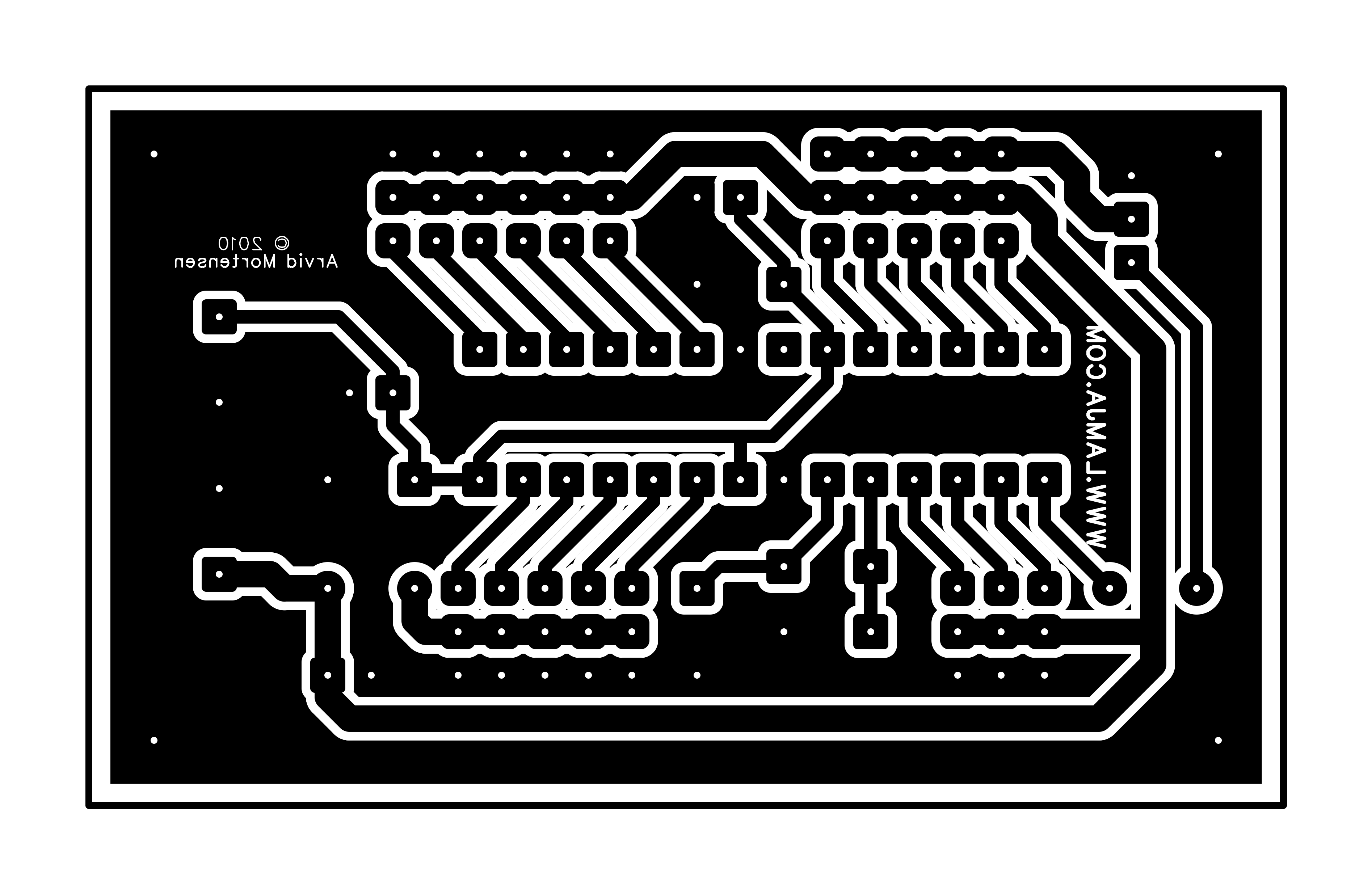
PCB bottom copper view from bottom (mirrored):
PCB top silk screen view from top:
PCB top silk screen view from bottom (mirrored):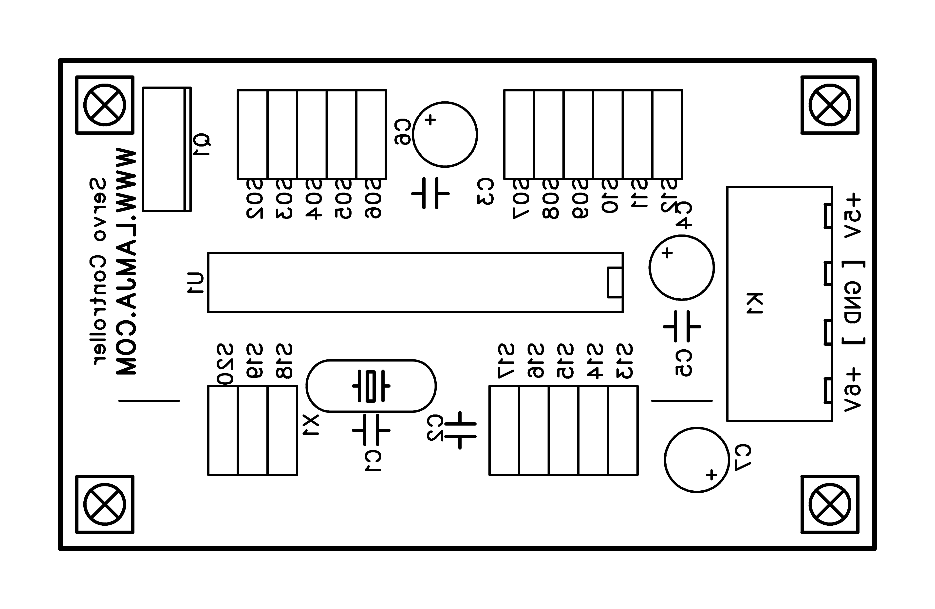 Partlist:
C1 = 22p
C2 = 22p
C3 = 100n
C4 = 10u
C5 = 100n
C6 = 10u
C7 = 10u
K1 =CMM 2×2-pol connector
Q1 = IRLZ14 or any MOSFET with same pin configuration
U1 = ATMEGA 328P With Arduino bootloader
X1 = 16MHz crystal
Two straps (wire) as marked on the silk screen.
S05 and S06 = Wire or 3 pin header for connecting servos
1 reistor 470 Ohm (The one connected to the switch)
1 diode (1A) for Connection from +6V to +5V
Switch (on/off)
2 Hobby servos
1 Rubber band
Some connection wire
Battery 4 x 1,5V AA case
4 batteries (AA)
Some wooden sticks
Wood glue
2 nails (small)
1 piece of foam
Code:
#include <Servo.h> #include <avr/sleep.h> Servo myservo2; // create servo object to control a servo Servo myservo1; int pos = 0; // variable to store the servo position int boxon =1; // Predefined positions for a spesific box/servo int S1fra = 1400; // from s1=Servo1 int S1mid = 1800; // Mid int S1mid2 = 1580; int S1mid3 = 1640; int S1til = 2050; // To int S2fra = 1784; //From s2=Servo2 int S2mid = 1200; int S2mid2 = 1000; // Almost on the switch int S2til = 770; int seq = 0; void setup() { myservo2.attach(13); // attaches the servo on pin 13 to the servo object (PB5) myservo1.attach(12); // attaches the servo on pin 12 to the servo object (PB4) pinMode(8, OUTPUT); // For the MOSFET pinMode(2, INPUT); // For the switch interrupt digitalWrite(2, HIGH); myservo2.write(S2fra); myservo1.write(S1fra); delay(600); digitalWrite(8, HIGH); delay(300); digitalWrite(8, LOW); // Put all unused pins to input high to save power. pinMode(3, INPUT); digitalWrite(3, HIGH); pinMode(4, INPUT); digitalWrite(4, HIGH); pinMode(5, INPUT); digitalWrite(5, HIGH); pinMode(6, INPUT); digitalWrite(6, HIGH); pinMode(7, INPUT); digitalWrite(7, HIGH); pinMode(9, INPUT); digitalWrite(9, HIGH); pinMode(10, INPUT); digitalWrite(10, HIGH); pinMode(11, INPUT); digitalWrite(11, HIGH); DDRC = 0; //Analog input 1/6 (PortC) set to input high also PORTC = 63; . //External interrupt INT0 EICRA=0; //The low level of INT0 generates an interrupt request EIMSK=1; //External Interrupt Request 0 Enable } void loop() { if(!boxon) //boxon should actually be called boxoff. Did a mistake here. { delay(500); digitalWrite(8, HIGH); //seq = int(random(0,10)); //If you want random… if(seq == 0)Sequense3(); if(seq == 1)Sequense1(); if(seq == 2)Sequense3(); if(seq == 3)Sequense9(); if(seq == 4)Sequense3(); if(seq == 5)Sequense5(); if(seq == 6)Sequense3(); if(seq == 7)Sequense7(); if(seq == 8)Sequense3(); if(seq == 9)Sequense2(); if(seq == 10)Sequense3(); if(seq == 11)Sequense10(); if(seq == 12)Sequense3(); if(seq == 13)Sequense8(); if(seq == 14)Sequense3(); if(seq == 15)Sequense6(); if(seq == 16)Sequense3(); if(seq == 17)Sequense4(); seq++; if(seq>17) seq=0; delay(100); digitalWrite(8, LOW); boxon=digitalRead(2); } else { //Set sleep mode, turn off MOSFET and servos set_sleep_mode(SLEEP_MODE_PWR_DOWN); sleep_enable(); pinMode(12, INPUT); digitalWrite(12, HIGH); pinMode(13, INPUT); digitalWrite(13, HIGH); PRR = 255; MCUCR |= (1<<BODS) | (1<<BODSE); MCUCR &= ~(1<<BODSE); EIMSK=1; sleep_mode(); // ZZZzzz… sleep_disable(); //Awake again… PRR = 0; pinMode(12, OUTPUT); pinMode(13, OUTPUT); } boxon=digitalRead(2); //If pin 2 is low, box is on and bonxon=flase } //Fra=From, Til=To (Sorry for some Norwegian variables) void Sweep(int srv, int fra, int til, int usec) { if(srv == 1) { if(fra <= til) for(pos = fra; pos < til; pos += 1) { myservo1.writeMicroseconds(pos); delayMicroseconds(usec); } else { for(pos = fra; pos>=til; pos-=1) { myservo1.writeMicroseconds(pos); delayMicroseconds(usec); } } } if(srv == 2) { if(fra <= til) for(pos = fra; pos < til; pos += 1) { myservo2.writeMicroseconds(pos); delayMicroseconds(usec); } else { for(pos = fra; pos>=til; pos-=1) { myservo2.writeMicroseconds(pos); delayMicroseconds(usec); } } } } ISR(INT0_vect) // Step rising edge interrupt. Switch flipped. { EIMSK=0; //Turn off interrupt boxon=digitalRead(2); //Read the switch a couple of times to avoid a nasty non working thing some times. boxon=digitalRead(2); boxon=digitalRead(2); boxon=digitalRead(2); boxon=digitalRead(2); boxon=digitalRead(2); boxon=digitalRead(2); boxon=digitalRead(2); boxon=digitalRead(2); boxon=digitalRead(2); } void Sequense1() { delay(700); Sweep(1, S1fra, S1mid, 3000); delay(1000); Sweep(1, S1mid, S1fra, 500); delay(1000); Sweep(1, S1fra, S1til, 1000); Sweep(2, S2fra, S2mid, 1800); Sweep(2, S2mid, S2til, 500); delay(100); Sweep(2, S2til, S2fra, 500); Sweep(1, S1til, S1fra, 500); } void Sequense2() { delay(800); Sweep(1, S1fra, S1mid2, 3000); Sweep(1, S1mid2, S1mid3, 1); delay(120); Sweep(1, S1mid3, S1mid2, 1); delay(120); Sweep(1, S1mid2, S1mid3, 1); delay(120); Sweep(1, S1mid3, S1mid2, 1); delay(120); Sweep(1, S1mid2, S1mid3, 1); delay(120); Sweep(1, S1mid3, S1mid2, 1); delay(120); Sweep(1, S1mid2, S1fra, 3000); Sweep(1, S1fra, S1mid, 3000); delay(1000); Sweep(1, S1mid, S1til, 1000); Sweep(2, S2fra, S2mid, 1800); Sweep(2, S2mid, S2til, 500); delay(100); Sweep(2, S2til, S2fra, 500); Sweep(1, S1til, S1fra, 500); } void Sequense3() { delay(50); Sweep(1, S1fra, S1til, 1); delay(1); Sweep(2, S2fra, S2til, 1); delay(450); Sweep(2, S2til, S2fra, 1); delay(200); Sweep(1, S1til, S1fra, 1); delay(400); } void Sequense4() { delay(500); Sweep(1, S1fra, S1til, 1); delay(1); Sweep(2, S2fra, S2mid2, 1); delay(450); Sweep(2, S2mid2, S2til, 30000); delay(1); Sweep(2, S2til, S2fra, 1); delay(200); Sweep(1, S1til, S1fra, 1); delay(400); } void Sequense5() { delay(1000); Sweep(1, S1fra, S1til, 1); delay(1); Sweep(2, S2fra, S2til, 1); delay(450); Sweep(2, S2til, S2mid2, 1); delay(110); Sweep(2, S2mid2, S2til, 1); delay(110); Sweep(2, S2til, S2mid2, 1); delay(110); Sweep(2, S2mid2, S2til, 1); delay(110); Sweep(2, S2til, S2mid2, 1); delay(110); Sweep(2, S2mid2, S2til, 1); delay(110); Sweep(2, S2til, S2fra, 1); delay(200); Sweep(1, S1til, S1fra, 1); delay(400); } void Sequense6() { delay(1500); Sweep(1, S1fra, S1til, 1); delay(1); Sweep(2, S2fra, S2til, 1); delay(450); Sweep(1, S1til, S1fra, 1000); delay(2000); Sweep(1, S1fra, S1til, 1000); delay(2000); Sweep(2, S2til, S2fra, 1); delay(200); Sweep(1, S1til, S1fra, 1); delay(400); } void Sequense7() { delay(500); Sweep(1, S1fra, S1mid, 1); delay(200); Sweep(1, S1mid, S1mid2, 1); delay(100); Sweep(1, S1mid2, S1mid, 1); delay(100); Sweep(1, S1mid, S1mid2, 1); delay(100); Sweep(1, S1mid2, S1mid, 1); delay(100); Sweep(1, S1mid, S1fra, 1); delay(200); Sweep(1, S1fra, S1til, 1); delay(1); Sweep(2, S2fra, S2til, 1); delay(450); Sweep(2, S2til, S2fra, 1); delay(200); Sweep(1, S1til, S1fra, 1); delay(400); } void Sequense8() { delay(200); Sweep(1, S1fra, S1mid, 1); delay(200); Sweep(1, S1mid, S1mid2, 1); delay(100); Sweep(1, S1mid2, S1mid, 1); delay(100); Sweep(1, S1mid, S1mid2, 1); delay(100); Sweep(1, S1mid2, S1mid3, 1); delay(50); Sweep(1, S1mid3, S1mid2, 1); delay(50); Sweep(1, S1mid2, S1mid3, 1); delay(50); Sweep(1, S1mid3, S1mid2, 1); delay(50); Sweep(1, S1mid2, S1mid3, 1); delay(50); Sweep(1, S1mid3, S1mid2, 1); delay(50); Sweep(1, S1mid2, S1mid3, 1); delay(50); Sweep(1, S1mid3, S1mid2, 1); delay(50); Sweep(1, S1mid2, S1mid3, 1); delay(50); Sweep(1, S1mid3, S1mid2, 1); delay(50); Sweep(1, S1mid2, S1mid3, 1); delay(50); Sweep(1, S1mid3, S1mid2, 1); delay(50); Sweep(1, S1mid2, S1fra, 1); delay(200); Sweep(1, S1fra, S1til, 1); delay(1); Sweep(2, S2fra, S2til, 1); delay(450); Sweep(2, S2til, S2fra, 1); delay(200); Sweep(1, S1til, S1fra, 1); delay(400); } void Sequense9() { delay(1000); Sweep(1, S1fra, S1mid, 2000); delay(500); Sweep(1, S1mid, S1mid2, 1000); delay(1); Sweep(1, S1mid2, S1mid3, 1); delay(50); Sweep(1, S1mid3, S1mid2, 1); delay(50); Sweep(1, S1mid2, S1mid3, 1); delay(50); Sweep(1, S1mid3, S1mid2, 1); delay(50); Sweep(1, S1mid2, S1mid3, 1); delay(50); Sweep(1, S1mid3, S1mid2, 1); delay(50); Sweep(1, S1mid2, S1mid3, 1); delay(50); Sweep(1, S1mid3, S1mid2, 1); delay(50); Sweep(1, S1mid2, S1mid3, 1); delay(50); Sweep(1, S1mid3, S1mid2, 1); delay(50); Sweep(1, S1mid2, S1mid3, 1); delay(50); Sweep(1, S1mid3, S1mid2, 1); delay(50); Sweep(1, S1mid2, S1mid3, 1); delay(50); Sweep(1, S1mid3, S1mid2, 1); delay(50); Sweep(1, S1mid2, S1mid3, 1); delay(50); Sweep(1, S1mid3, S1mid2, 1); delay(500); Sweep(1, S1mid2, S1mid, 5000); delay(1); Sweep(1, S1mid, S1til, 1000); delay(1); Sweep(2, S2fra, S2til, 1); delay(450); Sweep(2, S2til, S2fra, 1); delay(200); Sweep(1, S1til, S1fra, 1); delay(400); } void Sequense10() { delay(800); Sweep(1, S1fra, S1til, 30000); delay(1); Sweep(2, S2fra, S2til, 3000); delay(1); Sweep(2, S2til, S2fra, 3000); delay(1); Sweep(1, S1til, S1mid, 30000); delay(1); Sweep(1, S1mid, S1fra, 1); delay(300);}
There might be some typos in the code…
Better use this file : UselessMachine.pde <<<<<—–Download this!
Someone in europe who could build and sell this to me?
Really nice work. Would you be prepared to show me a circuit diagram? Thanks
sell me one or several pls 😀
Your project is amazing! Do you still have the schematic? if you do, can you send it to me?
thank you!
Please tell me the complete circuit diagram of the PCB, because I am not able to make a PCB. Thank you.
Hi. I will put together a shematic diagram. Coming up soon…
Sorry to be a nag, but any news on the schematic? Viewing your machine has created a group of simpleton electronics wanabees i’m afraid.
By making a machine so awesome you’ve created a rod for your own back. lol
I would seriously like to buy a set – please contact me if you are interested in selling a pair at minimal
Hello first compliment for your box is very good! I wanted to ask if you have a box to sell? greetings
This looks amazing! If you have plan to make and sell them, let me know. I’d buy one for a fair price!
Hey man, great stuff!
I’m doing this ‘useless’ machine for an arduino project for university, but I have a very basic understanding of it and cant vibe with this field very easily so I was wondering if you could break down how to make a simpler version of this, and break down of the code? It would mean so much.
Cheers.
I’m using 1.0.5 with Arduino Arduino UNO and received the error message below, would help?
useless_machine:18: error: stray ‘\’ in program
useless_machine:115: error: stray ‘\’ in program
useless_machine:154: error: stray ‘\’ in program
useless_machine:8: error: expected constructor, destructor, or type conversion before ‘void’
useless_machine:10: error: expected constructor, destructor, or type conversion before ‘extern’
useless_machine:19: error: expected constructor, destructor, or type conversion before ‘int’
useless_machine.ino: In function ‘void setup()’:
useless_machine:53: error: expected primary-expression before ‘.’ token
useless_machine:55: error: expected unqualified-id before ‘(‘ token
useless_machine.ino: In function ‘void loop()’:
useless_machine:69: error: ‘seq’ was not declared in this scope
useless_machine:70: error: ‘seq’ was not declared in this scope
useless_machine:71: error: ‘seq’ was not declared in this scope
useless_machine:72: error: ‘seq’ was not declared in this scope
useless_machine:73: error: ‘seq’ was not declared in this scope
useless_machine:74: error: ‘seq’ was not declared in this scope
useless_machine:75: error: ‘seq’ was not declared in this scope
useless_machine:76: error: ‘seq’ was not declared in this scope
useless_machine:77: error: ‘seq’ was not declared in this scope
useless_machine:78: error: ‘seq’ was not declared in this scope
useless_machine:79: error: ‘seq’ was not declared in this scope
useless_machine:80: error: ‘seq’ was not declared in this scope
useless_machine:81: error: ‘seq’ was not declared in this scope
useless_machine:82: error: ‘seq’ was not declared in this scope
useless_machine:83: error: ‘seq’ was not declared in this scope
useless_machine:84: error: ‘seq’ was not declared in this scope
useless_machine:85: error: ‘seq’ was not declared in this scope
useless_machine:86: error: ‘seq’ was not declared in this scope
useless_machine:87: error: ‘seq’ was not declared in this scope
useless_machine.ino: At global scope:
useless_machine:117: error: expected constructor, destructor, or type conversion before ‘void’
Resolved, to copy text with formatting code created small tab spaces that caused the errors.
Thank you!
Hi. Glad you find the error. Uploaded the file also, so it can be downloaded correctly. Link just above the comments.
I would like buy this. Can somebody sell it for me?
Get this error code on verify with Arduino Uno
pinMode(11, INPUT);
digitalWrite(11, HIGH);
DDRC = 0; //Analog input 1/6 (PortC) set to input high also
PORTC = 63;
.
//External interrupt INT0
EICRA=0; //The low level of INT0 generates an interrupt request
EIMSK=1; //External Interrupt Request 0 Enable
Seems to be the “.” after PORTC = 63;
Sorry, left out the error code
UselessMachine.pde: In function ‘void setup()’:
UselessMachine:57: error: expected primary-expression before ‘.’ token
UselessMachine:59: error: expected unqualified-id before ‘(‘ token
Hi.
I guess you copy the code from page? Try the download link instead. That would work better.
Hello first compliment for your box is very good! I wanted to ask if you have a box to sell? greetings
Hi first of all your box is amazing. Very cool really. I’m from Germany so sorry for my bad english. I build your box with the same Programm and the same PCB like you. It seems to work. If the Switch is on and the pcb is connected with the batteries the servos move. If i turn the Switch of the servos Ends the current Programm step and don’t move anymore. So far so good. Now the Problem. When i turn on the Switch again nothing happens. Only if i let the Switch in the on Position and disconnect the batteries and connect them again, the servos work in the same way i describe in the top. I realy don’t know why. I hope you understand my english and maybe you can help me with this Problem.
Greetings
Peter
Hi. I hope you used the downloadedble link for the program, and not copied the code from the page. There might be some wrong formatting in that text. I also had some problem with the switch not working, but only one of 10 cycles or so. So I added a few digitalread to “fix” that:
ISR(INT0_vect) // Step rising edge interrupt. Switch flipped.
{
EIMSK=0; //Turn off interrupt
boxon=digitalRead(2); //Read the switch a couple of times to avoid a nasty non working thing some times.
boxon=digitalRead(2);
boxon=digitalRead(2);
boxon=digitalRead(2);
boxon=digitalRead(2);
boxon=digitalRead(2);
boxon=digitalRead(2);
boxon=digitalRead(2);
boxon=digitalRead(2);
boxon=digitalRead(2);
}
But if it’s not working at all, I guess the interrupt is not set up properly:
//External interrupt INT0
EICRA=0; //The low level of INT0 generates an interrupt request
EIMSK=1; //External Interrupt Request 0 Enable
Thats what I can think of. Hope it helps.
And your English is as good or better than mine (I’m from Norway)
First of all thank you for the fast answer. So now first of all yes i used the downloadable code. So i think it is not the problem with the several read of the switch. But what do you mean with the interrupt is not set up? These programm lines are in the downloadable code or not?
Greetings peter
Hi.
Yes, if you use the downloaded code, the program lines are included. I’m not shure why you get this behavior. Is the switch connected from the pin from the ATMEGA328 via the resistor (470 Ohm) to GND? Then it should have worked. You can maybe try to lower the reistor a bit. There should be an interrupt occuring when the pin goes low.
It works thank you. But i had another question. How can i tell the programm to make the steps in random mode. I’ve read in your programm that it is possible but i don’t know exactly what i had to do. Sorry for the maybe stupid questions but thats one of my first bigger projects with microcontrollers. Especially with arduino
Greetings
Peter
Change from this:
void loop()
{
if(!boxon) //boxon should actually be called boxoff. Did a mistake here.
{
delay(500);
digitalWrite(8, HIGH);
//seq = int(random(0,10)); //If you want random…
if(seq == 0)Sequense3();
if(seq == 1)Sequense1();
if(seq == 2)Sequense3();
if(seq == 3)Sequense9();
if(seq == 4)Sequense3();
if(seq == 5)Sequense5();
if(seq == 6)Sequense3();
if(seq == 7)Sequense7();
if(seq == 8)Sequense3();
if(seq == 9)Sequense2();
if(seq == 10)Sequense3();
if(seq == 11)Sequense10();
if(seq == 12)Sequense3();
if(seq == 13)Sequense8();
if(seq == 14)Sequense3();
if(seq == 15)Sequense6();
if(seq == 16)Sequense3();
if(seq == 17)Sequense4();
seq++;
if(seq>17) seq=0;
Change to this:
void loop()
{
if(!boxon) //boxon should actually be called boxoff. Did a mistake here.
{
delay(500);
digitalWrite(8, HIGH);
seq = int(random(0,10)); //If you want random…
if(seq == 0)Sequense1();
if(seq == 1)Sequense2();
if(seq == 2)Sequense3();
if(seq == 3)Sequense4();
if(seq == 4)Sequense5();
if(seq == 5)Sequense6();
if(seq == 6)Sequense7();
if(seq == 7)Sequense8();
if(seq == 8)Sequense9();
if(seq == 9)Sequense10();
Thank you very much
Hi, is it possible to have one made that I can buy off you? This would make a really fun toy to sit on my desk at work..
Thanks heaps.
who wants such box ? and how much can u pay for it ? I can make such box
I too would like to buy one ready made but I noticed you haven’t replied to any similar requests…do you sell them?
I don’t have time to make kits for sale. And the prize will bee to high. So no, I will most probably never sell these. And they are not that hard to make yourself,
Do you sell the PCB? I can’t seem to find that part (or a substitute) anywhere. Thanks
certainly you don’t find the pcb anywhere. it is selfmade. and how arvid says the price to sell will be too high
I just want to help the people build a owen useless box. No reason to delte my comment. Not everybody has the knowledge and the material to build everything alone. So if someone needs help, material or a pcb contact me.
peterwagner321@gmail.de
Hello!
Sorry for my english, i am from Estonia.
I want to build my useless box as like you, and i think i can build it: wooden box, mechanics, PCB board. But i wasn’t make programming earlier…
Tell me please, is this hard? What i need for it?
And thank you very much for help!
Vitali.
Hi.
It’s pretty easy to program a chip. You’ll need an Arduino with the proper chip to program the chip. Lots of tutorials at http://arduino.cc/
Regards
Arvid
So, if i understood correctly, i can buy this http://store.arduino.cc/index.php?main_page=product_info&cPath=11&products_id=195#.Up4Hv8RdW6M
and two these http://store.arduino.cc/index.php?main_page=product_info&cPath=16_20&products_id=176#.Up4KdcRdW6M
and i can build my own box?
I read how to program chip, really easy.
Thanks.
Basically yes. What I did also, was to create my own PCBs, so I did not have to sacrifice the Arduino UNO. Then I bought some https://www.sparkfun.com/products/10524 bare Atmega328 chips to program with the Arduino and move them to my own PCBs. If you use the Arduino UNO in your Box, you will need higher voltage from the battery. Then the voltage may be too high for the servos.
Ok, i’ll try. Voltage is not a problem, i make something. Thank you for all.
Hi,
a BIG thank you for this project!
I want to build this with an Arduino UNO.
But at which ports I must connect the servos?
Do I modify your code for Ardunio?
Regards,
Torsten
Hi.
The ports used in the code is digital pin 12 and 13.
Code that sets the ports:
myservo2.attach(13); // attaches the servo on pin 13 to the servo object (PB5)
myservo1.attach(12); // attaches the servo on pin 12 to the servo object (PB4)
The code is made for an Arduino UNO…
Regards
Arvid
Okay.
The Switch is connect to PIN2 and the ground at the Arduino?
And the MOSFET to ground and the ground at the servos, right?
Regards,
Torsten
Hi,
thank you for assistance with the pin problems.
I build the machine with my Ardunio and lower the voltage from 6V for the servos to ~5V for the Ardunio with a diode.
But the servos running weird. The lid servo open and close the lid in a loop (open, close, open, close…) and the switch servo doesn’t respond. I see the orange light at the UNO when the lid servo is addressed and just a slight flicker when the switch servo is addressed.
Is this a code problem?
Cheers,
Torsten
Hi.
I’m not sure. Did you use the downloadeable code at the end of the page? I think there might be some character problem if you copy the code text from the page. It actually seems to me that the servos are mixed up, or the pin number are wrong. Strange…
Regards
Arvid
Hi,
I read about the copy and paste problem and download the code.
But I think it could be a power problem with my Arduino.
If I connect my notebook to the Arduino, both servos are working. The wrong direction but both are working. Can I invert the values of the servos?
If I disconnect the notebook I got the same problem (only one servo is working).
Torsten
To reverse the servos, you’ll need to edit the prdefined positions. You should anyway do this as two servos never are the same, and your box probably is not exactly the dimensions that I made.
Just play around with the values, from 600 to 2200 (some servos may work with 500 to 2500)
// Predefined positions for a spesific box/servo
int S1fra = 1400; // from s1=Servo1
int S1mid = 1800; // Mid
int S1mid2 = 1580;
int S1mid3 = 1640;
int S1til = 2050; // To
int S2fra = 1784; //From s2=Servo2
int S2mid = 1200;
int S2mid2 = 1000; // Almost on the switch
int S2til = 770;
Do you have a schematic diagram for the circuit?
Hello Arvid. Great stuff, man!!
There are dozens of versions of this “Useless Box” toys around the net however, your’s is the best Project overall, especially because of this page!! Congrats!
I’ve built three of these boxes to give to my nephews for XMas. The mechanical bits are done and the program loaded on the Arduino IDE (I decided to use the Random mod). Now, all I’m missing is the electronic schematic, so that I don’t have to trace the PCB for the proper connections.
Would you happen to have it handy? Would you be able to sent it to me by email or post it to the site, since so many people have already expressed their desire to have it as well?
I really want to finish them this weekend, so that I don’t miss the XMas deadline (sorry for the pressure!!)
Thanks in advance and best regards!
Hi. I will draw a schematic diagram today. In a some hours it should be up…
Regards
Arvid
I already did!!
May I have your email, so that I can send you my Fritzing file?
That way you can just double-check it and fix any mistakes I may have made (I am NOT well versed in that program!).
Afterwards you can post it here.
Thanks for replying so quickly!
Hi.
I did not see your post in time, so I have made a schematic diagram anyway. My email can be found on the “about” page : arvid@lamja.com
The schematic can be found above in the post.
Regards
Arvid
Thanks!
I’ll send you my file anyway.
Thanks for helping out with such shirt notice, and Congratularions again on your great project!
Merry XMas and a Great New Year!
Hi, love the box. Very fun project. Thanks for putting it up. This is my first introduction into circuits and im using your project as a teaching guide. Very helpful. I had a couple of quick questions if thats ok. I have a good handle on all the components, but and a little confused on the need for all the compositors. Can you provide a simple explanation for each compositor? I understand the purpose for the compactors connected to the timer and I think i understand the need for C7 and C4. But the purpose of the others seem a little confusing. I too am having an issue with the box not responding right away when the switch it flipped. It seems to be at random for its response. Sometimes it is right away and other times it will sit for a while. I originally started with you downloaded code, but after encountering the issue i tried working with it to fix it. I followed this code to see if it might help: http://playground.arduino.cc/Learning/arduinoSleepCode
Seem to be a dead end. Im thinking it has to do with power management which is why im asking about the compositors. Also, i didn’t have a 1ou 100v capacitor so i used a 10u 50v capacitor. My understanding is this would be find. Any input here also would be appreciated. Thanks for putting this up. Its be a very fun project to dive into. Here is the bulk of my current code (im excluding the sequence stuff because i didn’t really modify those):
#include

#include
Servo switchLeverServo; // create servo object to control a servo
Servo lidServo;
int pos = 0; // variable to store the servo position
int boxoff =1;
// Predefined positions for a spesific box/servo
int lidClosedPOS = 1400; // from s1=Servo1
int lidMidPOS = 1800; // Mid
int lidMid2POS = 1580;
int lidMid3POS = 1640;
int lidOpenPOS = 2050; // To
int switchLeverHiddingPOS = 2200; //From s2=Servo2
int switchLeverMidPOS = 1200;
int switchLeverMid2POS = 1000; // Almost on the switch
int switchLeverPushingPOS = 920;
/*
pins
*/
int lidServoPin = 11;//13
int switchLeverServoPin = 10;//12
int switchpin = 2;//2
int servosMOSFET = 9;
int seq = 0;
void setup()
{
pinMode(switchpin, INPUT);// For the switch interrupt
switchLeverServo.attach(switchLeverServoPin); // attaches the servo on pin 13 to the servo object (PB5)
lidServo.attach(lidServoPin); // attaches the servo on pin 12 to the servo object (PB4)
pinMode(servosMOSFET, OUTPUT); // For the MOSFET
digitalWrite(servosMOSFET, HIGH);
switchLeverServo.write(switchLeverHiddingPOS);
lidServo.write(lidClosedPOS);
delay(600);
digitalWrite(servosMOSFET, LOW);
// Put all unused pins to input high to save power.
int emptyPins[] = {4,5,6,7,8,12,13};
for(int i=0;i19) seq=0;
delay(100);
digitalWrite(servosMOSFET, LOW);
}
else
{
sleepNow();
}
delay(100);
boxoff=digitalRead(switchpin); //If pin 2 is low, box is on and boxoff=flase
}
Any help would be appreciated. Thanks!
Stupid autocorrect, im referring to capacitors not compactors. thanks
Hi. C3 and C5 is to get capasitors close to the two power pins on the ATMEGA 328. This is usually very important with any IC. C6 and C7 is electrolytic capasitors to pair up the ceramic ones (c3 and C5). Ceramic capasitors are good for high freq. filtering, and electrolitics are good at low freq. filtering and power reserve. These four capasitors are all on the 5V rail. I also included one capasitor on the 6V rail, to make the servos happy. I know it might be overkill, but it’s easier to put them there in the first place, rather having to search for a noise problem afterwards. Remember that the servos can generate some nasty noise.
The problem you have. It might be the resistor. I’m not sure why I put it tn there at all. The pin for the switch should be pulled up internally in the Atmega328, and it only need a Connection to ground to make the interrupt. You can try lowering this, or remove it completly. I’m not sure what will happend to the power usage of the atmega if you do.
Regards
Arvid
I don’t have an Arduino, would it be possible to buy a pre programmed ATMEGA 328P form you with random actions?
I really like this useless machine
Yes but you need a standalone arduino or a Lamja servo controller board.
Quick question, would it be possible to remove the ATmega328 from an arduino and drop an ATmega328 with Arduino Optiboot (Uno) from sparkfun load up the code here take it out and it be good to go?
Sorry I’m a total newb to arduino.
The atmega is shipped from Sparkfun only with the bootloader, you will need to record the “LAMJA firmware” in the new atmega. The best solution would be to buy an Arduino NANO USB and which is reduced in size, or an Arduino UNO to a slightly larger box.
I would like to buy one of these boxes. If possible please contact me.
Hey, guys. Need a little MOSFET help. I don’t want to spend 8 bucks for an IRLZ14, it says anything with a similar pinout, so would the IRF510 power mosfet work? I have one of those laying around. Just not sure and I can’t find a decent cross reference.
Thanks,
JB
I have connect everything and upload the code, but the servo didn’t move any idea how to identify the error?
I have tested the board and there is on everz field currency
Thanks
It would help me a lot if I know on which pin which voltage should be because there is no reaction :/
No currency in the mosfet left and right pin ?
Solved with multimeter problems with connections
im doing this project at school and was wondering if you could tell me more on the compositors in the parts list because my Systems teacher and i dont understand what the ” p, n, u ” are
pico, nano, micro
Hi,
First: sorry for my bad english 🙂
Is it possible to take a “ATtiny85” and not the ATMega328?
I’m not sure how many servos and digital in out you can use on that. But sure if there is enough pins.
Great project, just had a question on the dimensions of the box you built and the dimensions of the PCB. I plan on attempting to etch my own PCB at home and building this project for fun.
Yes I would also like to know the dimensions of the box.
This is an amazing project and while I’m extremely new to arduinos I’m eager to learn by trying my hand at building one of these myself.
Thank you for posting as much as you have so that the rest of us have something we can work off of.
can i program the atmega328p with this ? USB Serial Light Adapter ?
can i program the atmega328p with a raspberry pi ? or can i do it with a TXD RXD GND 3.3V cables ? how then.
Can i use a Arduino Mini 5 instead of atmega328 p ?
Hi,
thank you for this great project!
I never had tryed something with Arduino?
Are there any problems or changes in the code if I use a
STK500 Board (http://de.farnell.com/jsp/displayProduct.jsp?sku=3884429&gross_price=true&CMP=KNC-GDE-FDE-GEN-LISTINGS-SEPO-ATMEL&mckv=gnjKZRrt|pcrid|33492810667|plid|&gclid=CO7pgaC5jL0CFQcTwwod0n4ANg) ?
Or is it possible to put the code directly? You use the Arduino only as a programm interface?
Best Regards
Felix
Is your PCB-Layout an Eagle file?
It’s made with FreePCB.
That is 32 bit, so my code not work I guess. I think Arduino have released som 32 bit enviroment, but I have never tried it.
Where can I get the right and ?
I’ve I can build the electronic, i will send you the files to make the woodwork by CNC-Router.
Greetings!
Where I can get the right “Servo.h” and “avr/sleep.h”
http://arduino.cc/en/Main/Software#.UyDmzpVOV9A
IF you do not want to make a board just buy a Arduino mini pro on ebay for like $4
Hi Bogdan
Have you implemented this project with Arduino mini pro?
Could you please show me the scheme of connection?
someone could do with the Arduino one? could send a photo of the connections of the servos. and tips about the voltage and if you used a mosfet or not. Thank in advanced. Any help will welcome.
It says in the Schematic diagram: what pins to connect to.
Mosfet is to save battery. Eg. turn of servos when not in use.
Pretty slick! I don’t have the stuff to make the PCB… but I have everything else… I think I will pick up a proto board and give this a shot! Very cool.
Clever diode trick for the microcontroller voltage.
How would I wire the servos if I just wanted to use an UNO, two servos, and a 5 volt power supply from the wall? I see the signals from the servos go to pins 12 and 13, the switch goes to pin 2 with a 470 Ohm resistor. I take it the servo ground wires would go to the GND pin and the servo power wires would go to 5v pin and the switch, correct?
What is that box you used? Is that something you made yourself, or did you use a sigar box or something similar? I like how it doesn’t seem to show the opening door (at least on the video) and just looks like a box with a switch on top.
Hi.
I made it myself. I used small wood sticks, glue and a lot of sanding. And yes, it was one of my intensions to make it look like there is no lid when it’s closed.
Best Regards
Arvid
It’s the best I’ve seen on the net so far. Definitely sets the bar 😉 Guess I’ll have a nice hobby project for the time to come.
Thanks! 🙂
Hello,
when I try to compile the code I get this errors:
UselessMachine:109: error: ‘BODS’ was not declared in this scope
UselessMachine:109: error: ‘BODSE’ was not declared in this scope
Any ideas how to solve that?
Thans!
Use the download link for the code. I think htere are some crap if you just copy it from the page.
I’m trying to build this with ATmega8 instead of Atmega328 and got stuck at the code.
I used Arduino IDE then i choose “Tool -> Board ->Arduino NG or w/ Atmega8” to compile the code. I got this message
“UselessMachine:61: error: ‘EICRA’ was not declared in this scope
UselessMachine:62: error: ‘EIMSK’ was not declared in this scope
UselessMachine.ino: In function ‘void loop()’:
UselessMachine:110: error: ‘PRR’ was not declared in this scope
UselessMachine:111: error: ‘BODS’ was not declared in this scope
UselessMachine:111: error: ‘BODSE’ was not declared in this scope
UselessMachine:113: error: ‘EIMSK’ was not declared in this scope
UselessMachine.ino: In function ‘void __vector_1()’:
UselessMachine:167: error: ‘EIMSK’ was not declared in this scope”
I think there is a problem with sleep mode on Atmega8, maybe it’s different. Is ther any solution for this ?
Hi. Not sure. Haven’t worked with Atmega8 before. But your’e probably right.
Can you explain the code in detail for me, maybe it will be a little help.
pinMode(8, OUTPUT); // It’s mean INT0 as output
pinMode(2, INPUT); // switch will trigger the int
digitalWrite(2, HIGH); // when it’s LOW so u have to made it HIGH
delay(600);
digitalWrite(8, HIGH); // why here is HIGH
delay(300);
digitalWrite(8, LOW); // then LOW
DDRC = 0; // i dont understand from there, please help.
PORTC = 63; // Where i can read about this
//External interrupt INT0
EICRA=0; //here also
EIMSK=1;
And a whole code there :
//Set sleep mode, turn off MOSFET and servos
set_sleep_mode(SLEEP_MODE_PWR_DOWN); // this is the most saving energy mode
sleep_enable(); // then enable it
pinMode(12, INPUT); // why set this pin input and high there
digitalWrite(12, HIGH);
pinMode(13, INPUT);
digitalWrite(13, HIGH);
PRR = 255; // I need expain form there too
MCUCR |= (1<<BODS) | (1<<BODSE);
MCUCR &= ~(1<<BODSE);
EIMSK=1;
sleep_mode();
// ZZZzzz…
sleep_disable(); //Awake again…
PRR = 0;
pinMode(12, OUTPUT);
pinMode(13, OUTPUT);
Thank you.
Hi. EICRA, EIMSK, BODS, EIMSK and so on are Control register for various function in Atmega328. If you use anther microprosessor you will need to read the datasheet for that chip: http://www.atmel.com/images/atmel-2486-8-bit-avr-microcontroller-atmega8_l_datasheet.pdf
I see f.ex. that interrupt register in Atmega8 are called GICR and GIFR. Since this code uses interrupt and Power save, there might be some work to port it to antoher microprocessor.
Regards Arvid
have you complete the machine with atmega8?
can you share me the code with atmega8. I’m a newbie so i can’t write the code by myself. Thanks you :))
Great project – going to start building it now.
There is a typo I picked up in the code (from the link)
PORTC = 63;
.
//External interrupt INT0
The period shouldn’t be there.
Awesome!
I’m trying to build this using an Arduino Mega 2560 (is the board I use for experimenting). The code (once removed that missing period) doesn’t even compile. I have to comment out some code on the setup:
****************************
else
{
//Set sleep mode, turn off MOSFET and servos
set_sleep_mode(SLEEP_MODE_PWR_DOWN);
sleep_enable();
pinMode(12, INPUT);
digitalWrite(12, HIGH);
pinMode(13, INPUT);
digitalWrite(13, HIGH);
//PRR = 255;
//MCUCR |= (1<<BODS) | (1<<BODSE);
//MCUCR &= ~(1<<BODSE);
//EIMSK=1;
sleep_mode();
//ZZZzzz…
sleep_disable(); //Awake again…
//PRR = 0;
pinMode(12, OUTPUT);
pinMode(13, OUTPUT);
}
boxon=digitalRead(2); //If pin 2 is low, box is on and bonxon=flase
}
*****************************
I've read that it has something to do with the board you are using… does somebody have the equivalent code for my original arduino?
Arvid,
Great project, really want to make one using the Arduino Uno. Does anyone have a wiring diagram and components list for this method please? Also is there any drawings of the servo arms? Thanks again.
Hello, very nice project! Can someone translate it for an arduino board? A connectiondiagramm would be fine!
Hope someone can do this!
Greetings Felix
Thanks for posting this great project. It was so much fun to watch the YouTube, that as an abject and absolute know-nothing of way too mature age, I was inspired to purchase a beginning Arduino kit, some books on electronics, and do a bunch of web research.
After a few weeks, I now have a working model using a Nano on a proto-board and now know enough to have modified to code to suit me (it now starts our un-grumpy and becomes more grumpy before going random), added some LED “eyes” and did other things. I’ve more fun than the proverbial barrel of monkeys.
Thank you so much. Never too old to learn.
Pop Jack,
Can you please post a video of your machine? Would love to see it as I was thinking about building one myself and most of the stuff posted by others is way above my head. You’re the first one to make this seem buildable by mere mortals.
Here you go: http://youtu.be/fOPLIaYzPeI
I got mine working on a beginner UNO Arduino kit board and then used a Arduino Nano on a board in the final box. It took some time, but was a great learning experience for me.
Here is a video of it still working on the board- you can see the breadboard in the background:
http://youtu.be/dUCZSTjaIsE
Really nice work. I like the eyes.
Would you share your code with us? That’s a fantastic addition to the original box.
Hey, awesome project, but the code is outdated and needs to be converted (everything happens automaticly in the Arduino SDK) but i was wondering if anything is getting lost in while the presses…? :/
The random Method didn’t catches all sequences, most of the special ones aren’t proceeded at all.
So maybe a new version of the code would be required for further compatibility.
As i used an Arduino Uno it was quite difficult for an bloody beginner to apply your instructions; it works, but e.g. i left out the diod because it wasn’t working correctly with it and i used some other parts – i don’t know if i did some terrible mistakes, but it works, but im quite sure there are some unclean circuits…
Ah, i solved the first problem, the random number was only from 0 to 10 but there are 17 sequences and the coolest are 11-17, and the following lines
//seq++;
//if(seq>17) seq=0;
are only for not random and need to be deleted or commented (//) for properly functioning of random sequencing.
I’m up to coding some more sequences to increase the variety.
Hi 1st this is cool
I want to build this my only problem is I am extremely new to arduino I have never worked with it but I cot myself Intel Galileo and would really like to build this I get an error when I want to upload to the board I am sure this is my mistake but we all have to learn some ware here is the error I am getting. Please keep in mind I know nothing (sketch_stupid.ino:2:23: fatal error: avr/sleep.h: No such file or directory
compilation terminated.)
Hi.
I gues that is because the sleep function on Intel chip is a lot different from the Atmega. You will have to remove the sleep code. Or rewrite it. I have no experience with Intel Arduino.
Regards
Arvid
Thank you for your reply
I will try this excuse me if I will still ask stupid questions but I am new at this
And this is an excellent project to learn
Thanks again
Hi Sorry to bother you again I have tried to disable sleep I think
this is my new error on an useless machine sketch that is build for an uno board I get it loaded on the intel but I can not get this code loaded.do you think this might be to-do with the intel board or me I am aware a do not know anything at this stage of arduino.
Arduino: 1.5.3-Intel.1.0.4 (Windows 7), Board: “Intel® Galileo Gen2”
UselessMachine.ino: In function ‘void setup()’:
UselessMachine.ino:55:3: error: ‘DDRC’ was not declared in this scope
UselessMachine.ino:56:3: error: ‘PORTC’ was not declared in this scope
UselessMachine.ino:57:1: error: expected primary-expression before ‘.’ token
UselessMachine.ino:60:3: error: ‘EIMSK’ was not declared in this scope
UselessMachine.ino: In function ‘void loop()’:
UselessMachine.ino:107:1: error: a function-definition is not allowed here before ‘{‘ token
UselessMachine.ino:408:1: error: expected ‘}’ at end of input
This report would have more information with
“Show verbose output during compilation”
enabled in File > Preferences.
Hi.
Try commenting out all lines with an error. Put // in front of line.I think I remember they are just to save power. And also make sure you download the code with the link http://www.lamja.com/blogfiles/UselessMachine.pde and not by copying the text.
Regards
Arvid
Thank you I apresiate your patience
I will try to do that
I will try doing this I have downloaded the code but I will download again maybe I got confused and copy’d the code.
Once again
Thank you
Thank you very much! A very interesting project! Decided to put myself the same! I used the Arduino Pro Mini. From your scheme left only: R1, Q1, D1, C7. Do I need to C3, C4, C5 and C6? Sometimes the servo that controls the lid stops not in the correct position. Maybe it’s because of the missing capacitors?
Hi. No I dont think you’ll need them. The Pro Mini should take care of that trasient current.
I wonder why then the servo is not working?
my servo is installed upside down. I wrote under his box like this: // Predefined positions for a spesific box / servo
int S1fra = 1400; // From s1 = Servo1
int S1mid = 1000; // Mid
int S1mid2 = 1120;
int S1mid3 = 1060;
int S1til = 830; // To
int S2fra = 1714; // From s2 = Servo2
int S2mid = 1200;
int S2mid2 = 810; // Almost on the switch
int S2til = 720;
Maybe somewhere else you need to change any data on the servo? For instance initialization servo or something else?
Servo1 races occurs at the end of each command. She abruptly goes for reading S1til, sometimes even heard a crunch in the servo! I changed the servo, the other is the same! It is a pity to lose the servo! I will accept any help!
Hi. You may have to experiment on each servo to se what angles it will handle. Not every servo hadles the same extreme angles. That meaning what is the maximum and minimum angle for that servo. If you set the angle to high or low, the servo will stop and make a humming sound.
I stand servo hextronik HXT900. Operated from 700 to 2300. I think it exposed me reading – her missing. Several times it can open and close normally. But then … it is like a mad! Very dangerous jerks! Could this be what I use IRFZ44N?
Hi. That may be some interference or trasient voltages. Try putting a capasitor near the power for the servo.
Or it may be a defective servo.
10mf put down – nothing helped, put 1000mf – all worked fine cycles! now to drive a little bit, I hope there was a problem! Wery Thаnks!
Hi, this my version of your box.
https://youtu.be/peVV-MXrMkY
Nice work.
Hi, thanks for that but I only copied your design.
Paul.
Hi,
I love your Moody Useless Machines.
Is possible to buy it assembled?
thank you
Can we replace the more expensive Mosfet with with a BJT transistor?
Hi. I guess so. But not sure how to best connect it. Think you’ll need some resistors also then.
Hello! what circuit connected to the arduino? For firmware atmega328 arduino or some other features in this device performs ?
This i an Atmega328 chip connected like an Arduino with an extra MOSFET for controlling the power to the servos. The program on the Atmega is programmed with the Arduino enviroment with the code listed above.
Thanks for the answer. If I understand you correctly , I write code in atmega328 and the device will work. I do not quite understand the purpose of Arduino in this scheme .
Arduino is the Windows program that compile the C code tha I wrote to machine code used by the Atmega328.
Hello! I am trying to put together a kit for my dad as a gift for Christmas… he is an electrical engineer but I unfortunately have no clue what any of this is. Is there any possible way for you to make a parts list that the non-savvy people could use to at least buy all necessary parts for someone who would know how to use them??? Thanks. I hope that makes sense!!
Hi.
The easiest way is to buy a complete Arduino. And not create a PCB yourself. Below is a list of items you should get around with.
Pretty good seller on ebay:
1x: UNO R3 ATmega328P http://www.ebay.com/itm/New-UNO-R3-ATmega328P-CH340G-USB-Driver-Board-USB-Cable-For-Arduino-DIY-/201206976304?hash=item2ed8decf30:g:uHgAAOSwosFUU04G
1x: Plastic Battery Storage Case Box Holder For 4 X AA http://www.ebay.com/itm/Plastic-Battery-Storage-Case-Box-Holder-For-4-X-AA-4xAA-2A-6-0V-wire-leads-/200943447534?hash=item2ec929adee:g:ThcAAOxy9nhSIo-t
1x: IRLB3034 HEXFET Power MOSFET TO-220 http://www.ebay.com/itm/IRLB3034PBF-IRLB3034-HEXFET-Power-MOSFET-TO-220-/311484916477?hash=item4885f2a2fd:g:PH8AAOSw5VFWIMaw
1x: 1N5406 Diode 3 Amp http://www.ebay.com/itm/10PCS-1N5406-Diode-3-Amp-600-Volt-3A-600V-Brand-NEW-/311427883371?hash=item48828c616b:g:xu0AAOSwgQ9V09X9
1x: Toggle Switch http://www.ebay.com/itm/2PCS-Mini-6A-125V-AC-SPDT-MTS-102-3Pin-2-Position-On-on-Toggle-Switch-Practic-/400984156431?hash=item5d5c84a90f:g:eIEAAOSwjVVV2unS
1x: Resistor Bag 20 kinds http://www.ebay.com/itm/1-4w-Resistance-1-Metal-Film-Resistor-Bag-20-kinds-Each-20-Total-400pcs-top-/201186879447?hash=item2ed7ac27d7:g:03kAAOSwajVUMljx
1x: 1000uF 10V 105°C Radial Electrolytic Capacitor http://www.ebay.com/itm/10Pcs-1000uF-10V-105-C-Radial-Electrolytic-Capacitor-8x12mm-/311231407032?hash=item4876d663b8:g:GvoAAOSwDwtUnR52
1x: Breadboard Jumper Cable Wires http://www.ebay.com/itm/65Pcs-Male-to-Male-Solderless-Flexible-Breadboard-Jumper-Cable-Wires-For-Arduino-/201005528152?hash=item2eccdcf458:g:59IAAOxy63FSr6zq
Unknown seller:
2x: Standard Servo http://www.ebay.com/itm/1Pcs-High-Speed-Torque-Standard-Servo-for-S3003RC-Car-Helicopter-Airplane-Boat-/171953748453?hash=item28093df9e5:g:QpwAAOSwNgxWC9~j
Additional stuff you’ll need:
Wood and tools to make a box with lid that moves.
Regards
Arvid
thank you soooooo much!!!!!!!!!!!!!!!!!!!!!!!!
But I’m not sure if you’ll get all from Ebay soon enough for christmas.
This is Samantha’s Dad, I have the parts listed above. Is the 1000uF capacitor you had her order to be used across the batteries in place of C7 on your diagram?
Hi. Congrats with the gift. I thouth 10 micro was a little low to filter out noise from the servos. There has been some problem with noise from cheap servos. I would at first try to put it near the servos + and – on the other side of the mosfet. That would make sure the capasitor do not leak current from the battery. If you are stll experience noise issue, ie the servo moves irregular, move the cap to the battery, like C7.
Regards
Arvid
Hi. When i’m at it. The diode is supposed to lower the voltage from the battery 6V to appr. 5V. You’ll need to feed this 5V diectly into the 5V pin on the Arduino. If you are powering the arduino from USB when programming it, do not connect the 5V.
Regards
Arvid
I have completed the project. I used the Arduino UNO board and two Futaba S3003 servos. Starting with Arvid’s schematic design, I did the following:
I kept the 470 ohm resistor (R1) and the MOSFET (Q1).
I used only one capacitor (1000uF) and placed it across the battery pack.
I did not need the crystal oscillator because it is already part of the Arduino board.
I used a 1N4001 diode instead of MUR420G for D1.
I used a rocker switch instead of a toggle switch for the top of the box.
I added a toggle switch immediately out of the positive side of the battery pack and placed it inside the box – this allows all power to be shut off when not in use.
I added 5 blue LEDs (IL142) to light up the inside of the box when the rocker switch was turned on. The cathode side of the LEDs are connected to the “non-ground” side of the rocker switch, the anode side of the LEDs are each connected to a 100 ohm resistor, and the other side of the resistor is connected to cathode side of D1 (which is the +5V power for the Arduino).
I added four 0.1 watt, 8 ohm mini-speakers. The first pair of the speakers is connected in parallel. The second pair of the speakers is also connected in parallel. The negative end of the first pair is connected to GND and the positive end is connected to the negative end of the second pair. The positive end of the second pair is connected to Arduino Pin 10.
The Arduino pin connections are as follows:
Pin 2 – interrupt signal from rocker switch through R1
Pin 8 – connected to Q1 gate
Pin 10 – connected to speakers as mentioned above
Pin 12 – connected to control of Servo 1
Pin 13 – connected to control of Servo 2
Pin GND – connected to GND from battery pack
Pin +5V – connected to cathode side of D1
In the program:
I added sound by inserting code from the Arduino library that plays tones.
I eliminated the power down code and instead placed a toggle switch inside to box to shut it down when not in use. I did this because the code got stuck in power down mode if the interrupt occurred at precisely the wrong time. I tried modifying the code but was unsuccessful. This is why I added the toggle switch.
I added a couple of sequences as well.
The box runs through every sequence once and then randomly selects them.
I’ve added a video link for you to see the box in operation.
Here’s the link:
https://youtu.be/QaYfOL0unew
Hi. Nice work! Liked the music.
Regards
Arvid
hello my name is Silvio, Thank you so much for your work. I have, however, a question of understanding ….. why is the MOSFET there, or what he has for a functional and purposeful. In ATMEGA 328P but a wakeup circuit is already intigriert
Greetings Silvio
Hi. The MOSFET is to switch off the current to the servos. so they don’t use any battery power when idle.
Regards Arvid
Hi.
I just have build this project and have a great problem.
The servos don’t work like in your video.
They turn several times to 360 degrees and hold on different positions
I use these here (http://www.servodatabase.com/servo/feetech/fs5103r)
The difference to your servos: My 6.0V: 0.16 sec/60° – Yours 6.0V: 0.14 sec/60°
What do I have to adjust that it works?
Greetings Tim
Hi. I see you use “Continuous Rotation Robot Servo”. That will not work with this application. You’ll have to use standard RC servos (180 degrees).
Regards
Arvid
Thank you for this answer.
Greetings Tim
Just wondering what happened to sequences 11 to 17 in the download sketch file? Can any one send them to me or re post them. Thanks
Hi. I never made those. I just linked them to other sequences. Guess my imagination got stuck… Feel free to make your own new ones…
Regards Arvid
Oh, Ok. I was just wondering as they where mentioned in one of the above post. Thanks for the quick reply though and keep up the good work. I have made one and plan on making a few more for friends and family as gifts.
Hello
Thanks for this great Project, can you send me Please the PCB bottom copper.
Greets Andy
Just click the pictures in the article. Or use these links:
http://www.lamja.com/wp-content/uploads/2013/07/bottom_copper_mirror.png
http://www.lamja.com/wp-content/uploads/2013/07/bottom_copper.png
/Arvid
Thank you very much.
greets
Andy
Please give .hex file from your .pde file. I can’t loaded by PDE file. thank you so much.
Just rename it to .ino I think that would be OK
I do not know much about electronics. I bought a load circuit for chip and it supports only the hex file. So I can rename your files .PDE => .HEX okay?
I think you will need to compile the C code in Arduino IDE and the use the .hex file from that. See http://forum.arduino.cc/index.php?topic=46866.0
OK. thank you very much.
Hi Arvid.
I bought a Arduino starterkit. (http://www.arduino.cc/en/Main/ArduinoStarterKit)
I realize this is not thing for me, i have made all the projects in the guidebook and still do not have an idea what i am doing.
Therefore i have no problem to make it disappear into a useless box to never be seen again. Your box would be perfect “black hole” for my arduino.
But to understand how to connect all the components on the things included in the kit to make your useless box is a bit tricky for me. I understand an extra servo is needed. Is there anything more to I need to get except from the components in the Arduino starterkit?
The box and all the mechanical is no issue.
Would/could you make a “easy to understand”-sketch where you show me/us how to do?
Great job btw.
Mvh Janne
Bump
Thank you so much for the Code and the idea.
I built a box by myself and modified your code a bit.
just want to say (for those who need more memory).
I added two Variables one for actual position of Servo1 and one for actual pos of Servo2.
Deleted the simple pos store Variable and modified every Sweep using only 3 Parameters:
1. which Servo
2. to which position
3. speed
the from parameter is taken from the variable. After moving to the final position, it stores itself to the actual pos Variable. Here the Code from the Sweep part (sorry for the German parts). However, this modifikation reduces my memory use from 30% to 26% !
void Sweep(int srv, int zu, int usec)
{
if(srv == 1)
{
if(pos1 <= zu)
for(pos1; pos1 =zu; pos1-=1)
{
myservo1.writeMicroseconds(pos1);
delayMicroseconds(usec);
}
}
pos1 = zu;
}
if(srv == 2)
{
if(pos2 <= zu)
for(pos2; pos2 =zu; pos2-=1)
{
myservo2.writeMicroseconds(pos2);
delayMicroseconds(usec);
}
}
pos2 = zu;
}
}
Nice, that was smart..
I’m just trying to set the position values for the servos but I’m troubled understanding the values used here.. aren’t the values for the servo position using going from 0-179 ?
I’m using an arduino UNO waiting to receive a NANO..
I’m having a blast testing and assembling the electronics. Thanks for putting this out there and all guidance!! Now onto the box. A question…
– It doesn’t look like you screwed the servos in (to dummy blocks). What are folks doing instead? Epoxying them in or using double-sided tape? Seems like that would sure make it difficult to replace, or to adjust alignment of the servo that turns off the switch. Or are they attached some other way, or just wedged in between wood supports? If screwed in, the side of the box would have to be removable.
Hi. Epoxying did not stick well to the servo. So I used sticky tape and glue to the bottom and the side of the servo.
Regards Arvid
i can not get the program to up load on my uno
i new at this any help
Hi I wanted to show my Usless box. Thanks you so much for your help. That took me some time to set up, after failing to buld that atmega circuit of hell!! I finally decided to use an arduino Nano. It was a great experience.
Awesome ! Very nice job ! Can you give me a schema of your arduino nano connections ? thanx
And dont understand the use of the MOFSET, can somebody explain me ?
Is it necessary?
If it´s possiple to change the sketch so that i don´t need a Mosfet and the box never sleep! after a few sequences the goes off! my english is not the best!
Yes. But then the box will be drained for power pretty quick.
Put the working code, code of the link does not work, when you compile in the Arduino IDE produces errors.
figured out, everything works in the code the error was.
Hi Arvid,
I was so enchanted by the first one of your boxes I built that I built twelve more and gave them to friends and family for Christmas. This was over a year ago and now I’m having a strange problem with the one I kept for myself. It’s been working perfectly but all of a sudden it has quit working (no response to the switch). I have to remove any battery and put it back in to get it to start working again. I thought I was getting corrosion on a battery contact but that’s not the problem. Obviously, I have changed the batteries with all fresh but the problem persists.
I was wondering if you might have any suggestions. I was thinking that the MOSFET is starting to fail or some other component that is related to waking up. It does work for about a day after removing and replacing a battery. Then it fails again.
Any help would be appreciated.
Might be that the mosfet is not turning off the power to the servos. They will then drain batteries quickly. Might be a bad connection or something…
Arvid, the thing is that the batteries are not draining. I just remove a battery and then reinstall the same battery and it starts working again. I’ll have to study the electrical schematic and try to figure out which component can cause the failure I’m seeing. I don’t want to have to make a complete new circuit board.
A bad connection will not be fixed by simply removing and then reinstalling the same battery.
Sorry, I never did publish the solution to the problem I reported over a year ago. The problem I described above was caused by the switch – apparently, it was starting to fail and was starting to “bounce” (Google “switch bounce arduino” for more info).
I replaced the switch and the box started working perfectly again.
If you notice in arvid’s code he has a bunch of lines of code repeated in one section of the program. That’s to prevent switch bounce from affecting the reading of the switch. If the bounce gets too bad those repeated lines won’t prevent the problem.
I have a similar problem. Sometimes the box will go through it’s whole sequence with no issues. Other times it is just dead in the water after I press the switch. It never stops in the middle of an action. It only stops between sequences, while it is waiting for me to flip switch. It just stops and won’t do next sequence, even though I pressed the switch. I have fresh batteries. Did the same thing with fresh and old batteries. To help reset the box, I added a power switch. If I tun the box power off, wait a minute, then power back on, then sometime it makes it all the way through. Other times it locks up beaten a different set of sequences.
Let me say I love your Project and I’m trying to follow it as my first Arduino project (also my first time making a PCB and only the 2nd circuit I have ever built) I have so many questions. I’m trying to follow your plans exactly but I’m a little confised being so new to all this. First, on the PCB all the extra holes that have nothing plugged into them and the copper traces that go to them, what’s the point of those? are they really necessary? Second, I see you used 100v 10uF capacitors, if I only have 25v 10uF capacitors will that still work? My last question, I have found almost all the parts, I just can’t seem to find the CMM 2×2-pol connector. I found something similar but it won’t work with the board, do you have a link to the part you bought? I can probably build this off of my UNO and use less components, but I’d rather try making my first PCB, plus I already bought most of what I need.
Also, I don’t know if you have a photo or if you’d be willing to take one but I’m trying to see the underside of the PCB with the components installed. just so I can get a better idea of how the components fit into the copper traces, thanks for any help you may give while I experiment with this.
Two of the boxes I made are given away. The third I don’t know where it is. I think I broke it for the photos and it probably lays in a box dismantled somewhere. Sorry.
Regards
Arvid
The extra holes are because I made a genral servo controller board that I reused. So you dont need those. The capasitors should be 10V or higher. I just used what I had laying around. The conntctor I used was this: https://www.elfadistrelec.no/no/rekkeklemme-for-kretskort-pitch-mm-horisontal-2p-stelvio-kontek-cmm/p/14837506?q=CMM+2%C3%972&page=3&origPos=3&origPageSize=50&simi=87.8 but you can use any connector that have 5mm spacing. For example: http://www.ebay.com/itm/20pcs-5mm-Pitch-2-pin-2-way-Straight-Pin-PCB-Screw-Terminal-Blocks-Connector-/271560005137?hash=item3f3a3cd611:g:3ekAAOSwDk5T1PiC
I appreciate the help. I guess I might try to figure out the placement of the components to get the traces I need and which holes I need and hand draw the PCB. Hopefully, I get the connections right. Worst case scenario I have to sacrifice my UNO and use it instead of a PCB. thanks again.
So, I finally completed the build. It took me a while because this was my first attempt at something like this. I had to buy a soldering station and learn to solder, had to buy a drill press and fix an old laser printer to make the PCB, it was a lot of work and a lot of learning. Today I finished all connections and flipped the switch and got zero movement except for a small twitch for half a second. I don’t know if it’s the code or maybe I wired something wrong or didn’t solder something correctly. I checked for continuity and have it on all circuits. Is there anything you can suggest me trying to troubleshoot?
Hi. Good job. If you have an oscilloscope, you can check if there is pulses for the servo on the pin from the Atmel chip. If not, you could connect a LED with a resistor in series to another pin on the Atmel, and program it to blink. Just so you know that the Atmel chip is operational, alive an kicking. You could also try to just make a simple test program to see if you get the servo to work without the mosfet. The mosfet is only there to save current when not in use. But if the mosfets pins are mixed, it will not work. Go to http://www.arduino.cc (https://www.arduino.cc/en/tutorial/sweep and https://www.arduino.cc/en/tutorial/blink)to check for tutorials for how to connect servos and LEDs, and test bit by bit.
/Arvid
Thanks Arvid, I think the servos might be the issue. one is definitely broken, it spins past 360 degrees. the other one works fine and I tested it with the sweep function. I used the same MOSFET as you and the pins are correct, but this was my first ever PCB and my soldering skills weren’t all that great so I’m going to try to make it again, and replace the servos. I check for continuity, it’s all good, the voltage is good, I think the amperage is good and there are no shorts. after removing the broken servo the other servo would move but very slowly and only about 10% of the movement it was supposed to make. almost looked like dead batteries but they were brand new and as I said the voltage was correct for both the servos and the chip. thanks for all the help, this is a really fun project and I’ve learned so much, even if I haven’t gotten it working yet.
Um im using the sparkfun red board it currently doesn’t work, um can you make an only servio based one please. 😀
Hello,
i tried to build this, but i can’t get it getting “runnig”.
Everythings works fine, but the position of the servoarm is not as in the code.
Normally the arm should touch the switch at the position “770”.
The sleeping position of the arm is always good, but it won’t hit the switch!
Only in the sequence with the slow moving arm, the arm hits the button.
When the arm moves faster, it stops over the switch and won’t hit it!
Whats wrong?