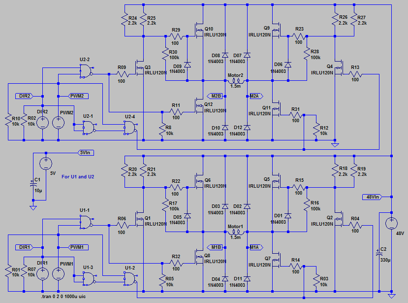
This is a double H-bridge that can be used with PWM to control the output current. It uses some NAND logic to make sure there will be no shoot-through shortening the supply voltage by opening both high-side and low-side MOSFET’s at the same time.
I started out this design actually using an extra voltage source (battery) for driving the high side MOSFET’s. Then R24, R25 R26 and R27 had 9V extra voltage than the MOSFETS.
I didn’t like that solution, and just removed the battery. And the design still worked. A drawback with poorly driven high-side FET’s is that the will produce some heat. About 6W with 12V supply. The second drawback is that the voltage across the motor will drop by 3V. So if you have 12V power supply, the motor only get about 9V.
My intension for this H-bridge was to use it for an 50V driver for bipolar stepper motor. And if you supply 50V, the motor will get 47V. So who cares if there is some heat generated. It’s easyer to put on a heat sink, than creating an extra powersupply feeding the upper FET’s. The current would anyhow be limited by the PWM.
I did use this with an Arduino, and it worked well. It’s not that great with stepper motors, because you can’t use chop to boost the performance without risking to burn the motor.
The design of the NAND-gates are described in a previous article: How to design a circuit from NAND-gates only,using a truth-table
The diodes would be better to change to some fast schottky ones for better performance.
I’ve used the IRLU120N’s for small-signal as well, because they are cheap and logic level. They are rated at 100V 10A, but only 48W. So the current will be limited at higher voltages. You also need som bigger heat sink at higher voltages.
I have only tested this design for 20V and about 1.5A
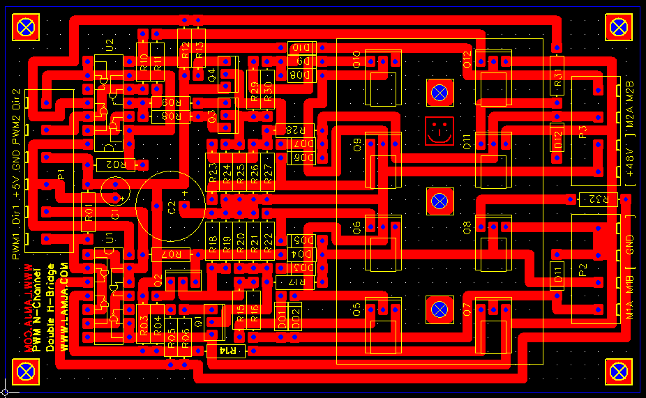
I used FreePCB to create the PCB layout:
1200 DPI PCB-files can be downloaded from the link in the bottom of this article.
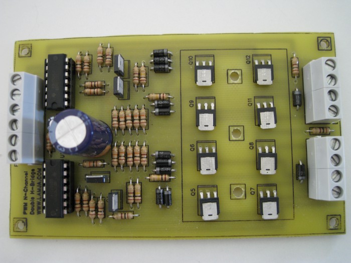
The finished board:
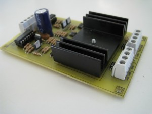
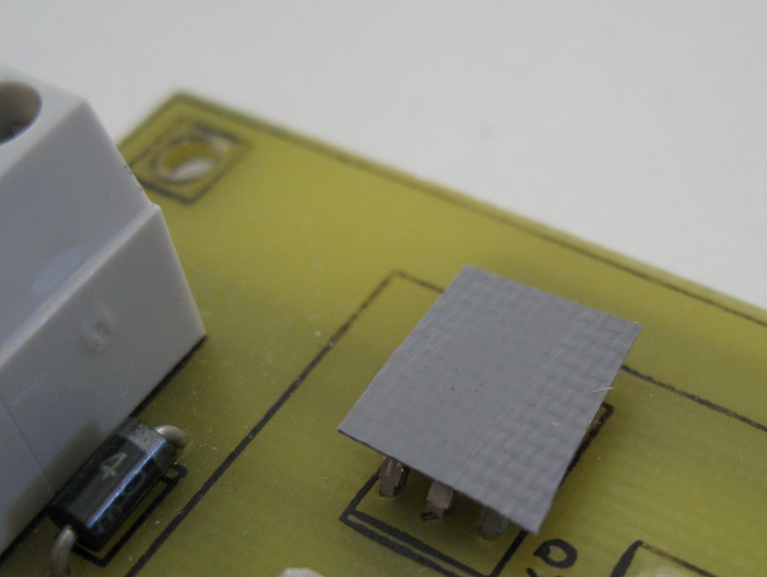
The heat sink MUST be isolated from the FET’s, so you have to use some isolating heat transferring film, between the FET’s and the heat sink. Shown in the picture below.
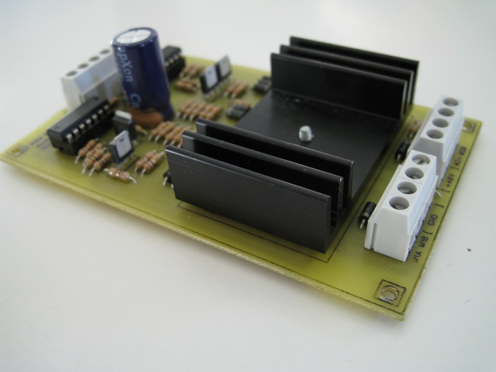
The finished board with heat sink:
Files:
http://www.lamja.com/blogfiles/Double_H-bridge_PartList.txt
http://www.lamja.com/blogfiles/Double_H-bridge_LTSpice.asc
http://www.lamja.com/blogfiles/Double_H-bridge_BottomCopper.png
http://www.lamja.com/blogfiles/Double_H-bridge_BottomCopperMirror.png
http://www.lamja.com/blogfiles/Double_H-bridge_TopSilk.png
http://www.lamja.com/blogfiles/Double_H-bridge_TopSilkMirror.png




Interesting… that doesn’t look terribly expensive.
hello this h bridge is for 10A ?
I would like connect this with a dc motor in 12 V and connect the h bridge with battery 12 v
Is that pcb homemade ?
What method do you use? The silkscreen looks really nice.
Yes it’s homemade. I use laser toner transfer method, also for the silk screen. I used a little oil on the silk screen so it don’t dry up. If it dries up it gets white, and is almost invissible.
Hi! Nice publishing and clip on youtube! 🙂
I was searching for information regarding H-bridge and speedcontroll by PWM so this is perfect. My motors are runnig on 24V and need up to 50 Amps in burst so I´m wondering if it would be possible to change the highside FET to IRLU8721PBF?
They have a lower “on resistance”, only 8,4 milliohm…
I guess so, but since the high side is not driven good enough, it will have no or little effect for the heat generated by the FET’s. There will still be 3V loss over the FET’s…
I meant Q5 -Q12 but on second thought I could change all the FET to IRLU8721PBF if that would work
Hi.
Why did you use diodes between motor windings and ground respectively power source. The IRLR/U120N have some diodes inside that does the same.
Thanks, Ben.
Can you publish your code on how you are controlling the Hbridge with the Arduino?
I love you board. I am a little confused on the coding of the pwm and the dir pins on the driver board.
I have similar dual hbridge; however, getting my mind on coding the pins is not working.
I love the silk screen on the top. Nice job!
great work i am trying to do this at home but i can’t tell what is the size of the board can you publish it.
best regards
Hi. If you use the high resolution png’s at the bottom of the post, those are 1200 dpi (6000 pixels wide). That means the whole Picture (not the Board) is 5 inches wide. I used Open Office Writer to print the png at 100%, and it sets the correct scale as 12,7 cm wide. Actual size of board is 116.84 mm x 71.12 mm i think. Not totally sure. I have too many versions of the board, and no rev numbering 🙂
hi
i Have problem from Driver Motor
please upload schematic for Driver DC Motor With power mosfet And PWM
Im using Arduino interface
tanx
Hi!
Thanx for posting circuit diagram, PCB layoit ans silk-screen.
I’ve been looking at your design for a while, and today, for the first time, located these.
I have only just started looking at the world of stepper motors and was particularly looking for something beyond the very generic controllers found on the internet.
I will post results as sonn as I complete my project.
Thanx again, for sharing!!
Danie Bosman
Hi!
I just wanted to inform all that many commercially available H-bridge driver circuits employ internal charge pumps to get the higher voltage for the high side mosfets.
This enables you to get satisfactory drive of the high side without additional power sources.